
Peak Level Indicator

The described circuit functions as a test equipment tool specifically tailored for sound reinforcement systems, such as guitar amplifiers. Its primary role is to facilitate the testing and calibration of audio equipment by allowing users to generate and manipulate audio signals effectively. The circuit typically incorporates a signal generator, which produces a range of test tones or signals that can be fed into the amplifier or audio system under test.
The design of the circuit may include several key components, such as operational amplifiers for signal conditioning, resistors for setting gain levels, and capacitors for filtering unwanted noise. Additionally, the circuit may feature variable resistors (potentiometers) to allow users to adjust levels and frequencies according to specific testing requirements.
Connections for input and output should be clearly defined, with input terminals for connecting the signal generator and output terminals for interfacing with the amplifier or sound system. It is essential that the circuit is designed to handle a variety of signal levels to accommodate different types of audio equipment.
Furthermore, the circuit may include LED indicators to provide visual feedback on signal presence and levels, enhancing usability during testing. Proper grounding and shielding techniques should be employed to minimize interference and ensure accurate measurements.
Overall, this test equipment circuit serves as a critical tool for audio professionals, enabling precise control and adjustment of sound levels throughout the amplification chain, thereby improving the overall performance and reliability of sound reinforcement systems.This circuit was designed to provide a valuable test equipment tool for sound reinforcement systems like guitar amplifiers and the like. Used in conjunction with a signal generator it can be of considerable help in setting and controlling levels through any amplifying chain.
🔗 External reference
Related Circuits

6502 fully simulated at the transistor level. The simulator can be run in your browser. They are also taking submissions for other ICs to model. The 6502 microprocessor, originally designed by MOS Technology, is a popular 8-bit CPU known for...
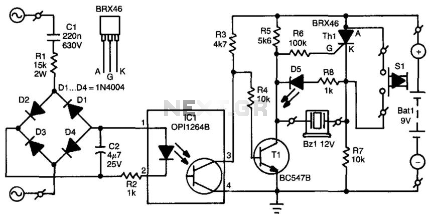
When the mains voltage is present at the input terminals, the transistor in the optocoupler is activated, T1 is off, and the silicon-controlled rectifier (SCR) Th1 is in the conducting state. As a result, both terminals of the piezoelectric...
The computer needs at least 180 millivolts peak-to-peak and the condenser microphone in my headset produces about 20 millivolts peak-to-peak into a 2.2k load with normal speech levels. There are USB ports on the machines, so I can use...
The controller consists of a liquid level sensor, a trigger controller, and a step-down rectifier circuit. The water level detection poles labeled a, b, and c form a bias circuit, functioning as a water level detector with components W1,...
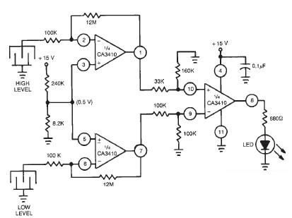
This liquid level sensor electronic circuit diagram utilizes a common CA3410 operational amplifier integrated circuit (IC). The sensor employs two plate sensors (or probes), one designated for detecting high liquid levels and the other for low liquid levels. If...
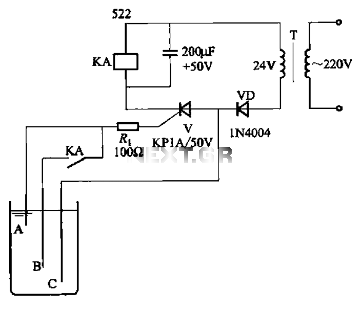
The circuit depicted in Figure 11-14 utilizes a unidirectional thyristor within liquid level automatic control systems. It incorporates electrodes that serve as sensing elements for detecting the level of water or other conductive liquids. The circuit features a current...