
Phone Message Flasher

The circuit utilizes a differential amplifier configured with transistors Q1, Q2, and Q3 to detect the presence of a ringing voltage on the telephone line. The hysteresis feature ensures that the circuit is less sensitive to noise and false triggering, providing reliable detection of ringing signals. When the phone rings, the voltage across the line increases, causing the differential amplifier to output a high signal, which turns on transistor Q4.
Transistor Q4 acts as a switch that enables the multivibrator circuit formed by Q5 and Q6. This multivibrator generates a square wave signal that drives the LED flashing mechanism. The flashing LED serves as a visual indicator that a call was received while the user was away. The LED is connected to transistor Q7, which controls its on/off state based on the output of the multivibrator.
The circuit is designed to maintain the activation of Q1 and Q2 as long as the line voltage remains above 9 V. This feature is crucial as it prevents the circuit from resetting prematurely when the phone is off-hook, ensuring that the LED continues to flash until the user acknowledges the missed call. Once the line voltage drops below the threshold, indicating that the phone is off-hook, Q1 and Q2 turn off, effectively disabling the circuit and stopping the LED from flashing.
This design is particularly useful for users who may not be near their phone when it rings, providing a clear indication of missed calls through the visual feedback of the LED. This circuit flashes an LED to indicate that your phone rang during your absence. A differential amplifier with hyste resis (Ql, Q2, and Q3) detects high line voltage (ringing), which turns on Q4, multivibrator Q5/Q6, and flashes the LED via Q7. Ql and Q2 remain on until the phone-line voltage drops to less than 9 V, which indicates an off-hook condition.
Related Circuits

The resistors may be rated at 1/8 watt. The zener diode can be either a 250 mW or a 1W component (the part number will differ). The electrolytic capacitor is a standard type, and its value can vary (larger...
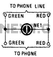
A neon lamp can easily be added to the phone line to act as a ring indicator. It is perfect for times when you cannot hear the phone. The integration of a neon lamp as a ring indicator in a...
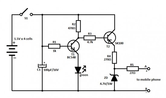
This is an ideal mobile charger that utilizes 1.5-volt pen cells to charge mobile phones while traveling. It can replenish a cell phone battery three or four times. The mobile charger circuit is designed to be compact and portable, making...
This circuit is a series of electric lamp flashers. It is designed to flash a 12V bulb approximately once per second. The configuration allows Q2 and Q1 to provide biasing, eliminating the need for a resistor. Typically, a cold...
%2B2%2BCH%2Bby%2BIC%2B%2BNE5532%2Bor%2BLF353.jpg)
This is a microphone preamplifier circuit model 2 CH. The circuit utilizes integrated circuits NE5532 or LF353 to amplify the sound signal from a dynamic microphone, increasing the power level for subsequent input into a stereo power amplifier. This...

Check the loop circuit for an automatic telephone answering system or a tone generator for use in reverse automatic repair. The loop circuit in an automatic telephone answering system is designed to detect incoming calls and activate the answering mechanism....