
pic based modified sine wave inverter

The proposed circuit design incorporates a microcontroller from the PIC family, which serves as the main control unit for the inverter operation. The two P-channel MOSFETs (F9540N) are employed as the primary switching elements, facilitating the conversion of DC voltage to AC voltage. The center-tapped transformer is crucial for stepping up the voltage to the desired level, providing a 230V output from a 12V input.
In this configuration, the microcontroller generates the necessary PWM (Pulse Width Modulation) signals to control the gates of the MOSFETs. The switching sequence of the MOSFETs is critical to ensure that they operate in a complementary manner, allowing for the creation of an alternating current (AC) waveform. The center-tapped transformer provides isolation between the input and output sides, enhancing safety and performance.
The F9540N MOSFETs are selected for their high efficiency and low on-resistance, which minimizes power losses during operation. The gate drive circuitry must be designed to ensure that the MOSFETs are fully turned on and off, which may involve the use of gate drivers or additional components to manage the switching speeds and prevent cross-conduction.
The circuit should also include protection mechanisms such as diodes for back EMF protection, fuses for overcurrent protection, and possibly a feedback loop to monitor the output voltage and adjust the PWM signals accordingly to maintain a stable output. Proper heat sinking for the MOSFETs is essential to manage thermal performance during operation.
Overall, this PIC-based inverter circuit design offers a compact and efficient solution for converting low-voltage DC power into high-voltage AC power, suitable for various applications in power electronics.hi am trying to make a pic based inverter circuit. the circuit uses 2 p-channel mosfets(f9540n) with a centre tapped 12-012/230v transformer. i.. 🔗 External reference
Related Circuits
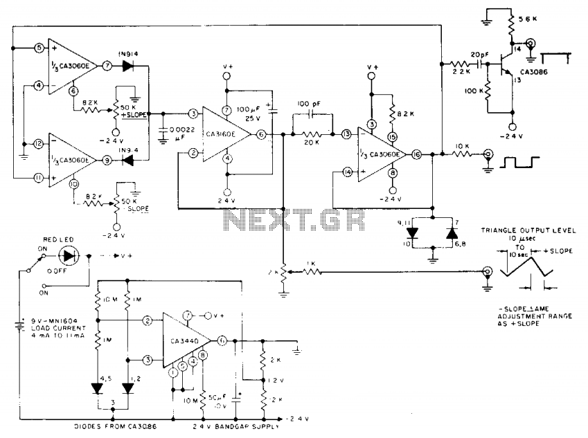
The circuit incorporates a CA3060 triple operational transconductance amplifier (OTA), where two units function as switched current generators, and the third amplifier controls them. A CA3160 BiMOS operational amplifier operates as a voltage follower, buffering a 0.0022 µF integrating...
A telephone line-based audio muting and light activation circuit. Frequently, when listening to music or watching television at elevated volume levels, it becomes difficult to hear a telephone ring, resulting in missed important calls. This circuit is designed to address...
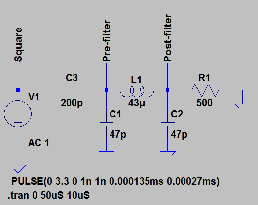
A sine wave carrier is required for a magnetic transponder system. Various crystal-based oscillators, such as the Pierce oscillator, can be complex to design and ensure proper functionality. An alternative approach involves using a square wave oscillator in conjunction...
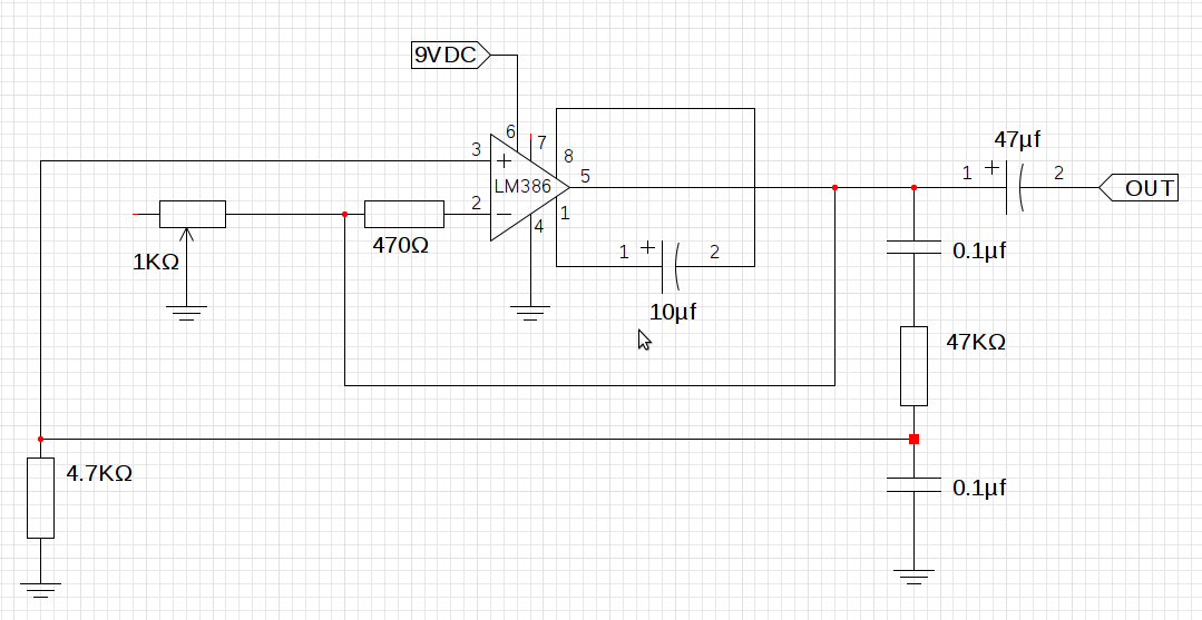
The design utilizes the LM386n-1 integrated circuit, powered by a single power supply to maintain a compact layout. There is a need to control the frequency, and the user is inquiring about which component values should be adjusted for...
The following circuit illustrates how to build a variable DC power supply circuit. This circuit is based on the 7805 IC. Features: other output is ... The variable DC power supply circuit utilizing the 7805 integrated circuit (IC) is designed...
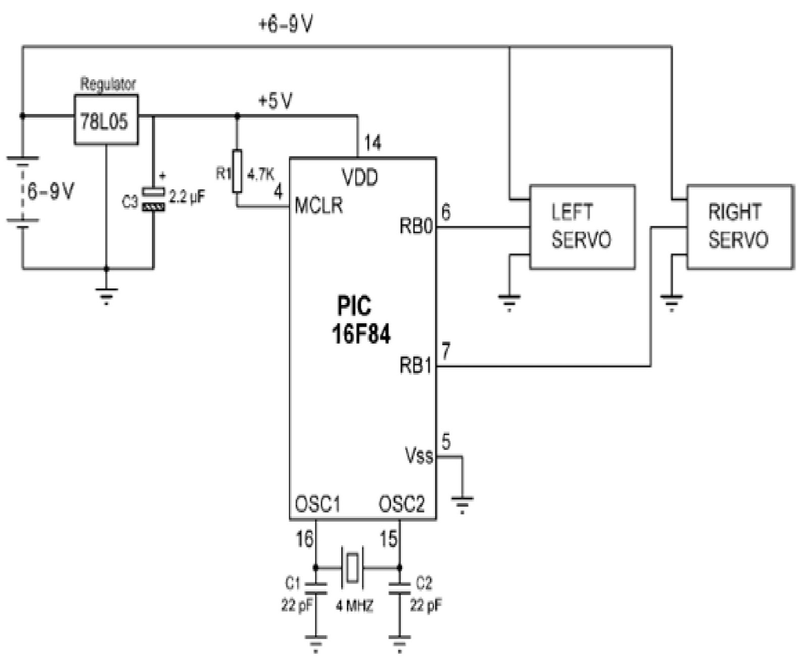
Mobile robots are utilized in various industrial, commercial, research, and hobby applications. This project focuses on controlling a mobile robot using servomotors. The robot is based on a well-known mobile robot called Boe Bot, developed by Parallax. The basic...