
pic PIC16f877A resets due to external noise

To address the issue of the PIC16F877A resetting when a load is placed on the relay contacts, it is essential to implement a robust circuit design that mitigates the effects of electrical noise and voltage fluctuations caused by the relay operation. A schematic diagram would illustrate the connections and components effectively, enhancing understanding of the circuit's layout.
1. **Relay and Diode Configuration**: Utilize a relay rated for the load being switched, ensuring that it can handle the inrush current without causing excessive voltage spikes. Replace the standard 1N4148 diode with a Schottky diode such as the 1N5819 to provide faster response times and lower forward voltage drop, which is crucial for handling flyback voltage generated during relay coil deactivation.
2. **Capacitance for Stability**: Place a capacitor across the diode, starting with a value of 10 µF, to absorb transient voltage spikes. Additionally, consider using a larger capacitor (100 µF) on the Vdd power rail to stabilize the voltage supplied to the PIC, especially during the relay's switching.
3. **Grounding and Layout Considerations**: Ensure that all grounds are properly connected, avoiding ground loops that could introduce noise. Use a star grounding configuration to minimize impedance and voltage drops. Pay attention to the layout of traces; keep high-current paths away from sensitive components like the PIC.
4. **Decoupling Capacitors**: Install decoupling capacitors (100 nF and larger) directly across the power and ground pins of the PIC. This will help filter out high-frequency noise and provide a stable voltage during rapid switching events within the microcontroller.
5. **RCR Network Implementation**: To prevent latch-up, implement an RCR network as suggested by Microchip in the PIC datasheet. This network will help manage the transient responses of the circuit, ensuring the microcontroller remains stable during operation.
By systematically addressing these points, the issues associated with the PIC16F877A resetting can be effectively mitigated, leading to a more reliable operation of the relay control circuit.Connect Relay with pic microcontroller and whenever I put Load on Relay`s Contacts PIC16f877a resets. I some time solve this problem by triggering another relay from basic relay attached to PIC. But this is not a solution. Can any one describes Why pic is affected with this relay spark. And what is really happening which causes pic to reset. Following things I have kept in mind while building circuit I never faces such problem in Atmel 89c51 microcontroller with same relay interfacing circuit. It is PIC who goes reset every time. But if do not connect any load to relay the circuit works fine. No reset occurs. Can any-one describes what is the issue with PIC 1. A schematic helps visualize what has been implemented, far better than a series of textual bullet points. 2. Replace the 1n4148 with a Schottky barrier diode like the 1n5819. 3. Try putting a capacitor (try 10 uF) across the diode. Anindo Ghosh Mar 12 `13 at 11:08 I have had this problem before. It was because of the collapsing on the power supply. Put a 10 uF capacitor on the Vdd power rail, and most probably your problem will be solved. Also, to avoid SR latch-up, as @Kaz noted, Microchip suggest an RCR network. Look for this information in the datasheet of your microcontroller. abdullah kahraman Mar 12 `13 at 11:23 @AbdulRehman Try increasing the capacitor to 100uF. For the replacement on 1N4148, search for "Flyback diode". About grounding. Every cable/trace has a resistance, but very small. However, with sufficient current, there can be a voltage drop. This means the ground will be at a higher potential than 0 volts. abdullah kahraman Mar 12 `13 at 12:41 @AbdulRehman While several excellent inputs have been provided already, hence my prior comment may be irrelevant, my suggestion for a Schottky comes from trying to alleviate flyback pulses from the relay coil at the source.
Typical flyback energy can require 1 to several amps of pulse current capability in the diode, 4148 doesn`t manage that. Also, the lower the diode voltage, the earlier in the pulse the bypass begins. Finally, between the Schottky and the capacitor, the impulse absorption would be more robust. A flyback diode as others suggested is really what you need there. Anindo Ghosh Mar 12 `13 at 16:37 This kind of symptom is to be expected from a number of bad design practises, including bad grounding, bad decoupling, bad power supply filtering, and bad layout.
You didn`t say much about this, which means you didn`t think much about grounding and it is therefore a possible problem. Just connecting everything to a ground net would be fine if nothing has any ground current. Of course various parts do. This current times the impedance back to the one point you get to call ground causes a offset voltage.
Don`t just think of ground in terms of DC. DC is the easy part. Consider the series inductance of any connection and then the high frequency ground return currents that run accross that connection. What is the relay switching Where does the current it is switching run Is the relay switch side completely isolated from the coil, or do they share a common ground If the latter, the substantial currents when the relay switches on its load could be causing ground bounce at the micro or other parts of the system.
This is clearly a problem in your case. You put 100 nF caps on both sides of the regulator, but you completely forgot to put bypass caps accross the PIC power and ground pins. This can cause power glitches local to the PIC when it switches internally, and can cause local ground glitches when those current transients travel along the ground net back to somewhere they can finally loop back to the supply.
You at least seem to have thought about this, but then only implemented it partially. 100 nF if pretty skimpy, particularly for the input of the regulator. I like to put 10 µF at the input of a regulator, 🔗 External reference
Related Circuits
This device uses a PIC12F615 to implement a capacitor discharge ignition system. When the switch (button) is closed, the PIC sends pulses to the IRF644 MosFet creating high voltage pulses to charge the 1.0 uf/250 volt capacitor. The voltage...
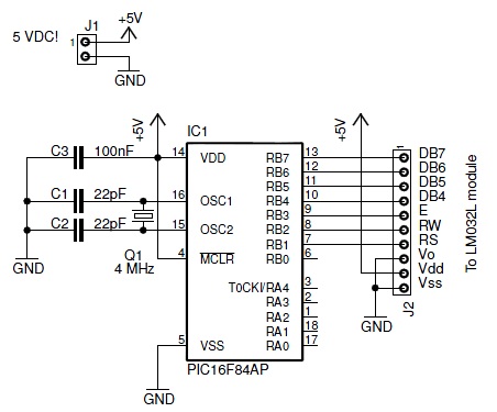
This document discusses an older LM032L LCD module from Hitachi. It details the process of making the module operational with a PIC 16F84A microcontroller. The module is capable of displaying two lines with 20 characters each. The initial step...
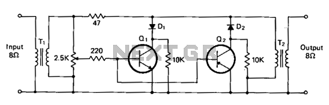
T1 and T2 are 600 to 8-ohm transformers (any transistor radio output transformers with 500 to 4-ohm impedance may be used). Q1 is a 2N2222 NPN transistor, and Q2 is a 2N2907 PNP transistor. D1 and D2 are 1N270...
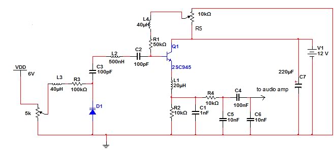
The circuit described is an FM receiver. When a 9V power supply is used, the circuit exhibits good performance. However, performance issues arise when an AC/DC rectifier or switch-mode power supply is utilized. The FM receiver circuit operates by demodulating...
SPICE is the most commonly used analog circuit simulator today and is enormously important for the electronics industry. SPICE is a general purpose analog simulator which contains models for most circuit elements and can handle complex nonlinear circuits. AIM-Spice...
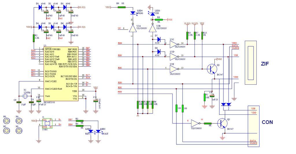
GTP USB PIC Programmer (Open Source). This project includes the GTP USB (not plus or lite). The schematic, photos, and PCB have been developed by PICMASTERS. The GTP USB PIC Programmer is an open-source device designed for programming PIC microcontrollers...