
PIC Programming how to get started

The PIC16F84 microcontroller serves as a versatile and powerful component for various electronic projects. As a microcontroller, it integrates essential functionalities such as program storage, input/output operations, and timing control within a single chip, significantly simplifying circuit design. The chip operates on a 5V power supply and features 13-bit instruction architecture, allowing it to execute a wide range of commands efficiently.
In practical applications, the PIC16F84 can be programmed using various software development environments, such as MPLAB X IDE, which supports assembly language and C programming. The programming process involves writing source code that defines the desired behavior of the microcontroller, which is then compiled into machine code that the PIC can execute. This flexibility allows for the implementation of complex logic and control systems that would otherwise require extensive discrete component arrangements.
For example, a project utilizing the PIC16F84 could involve creating a binary counter circuit. In this design, the PIC would replace traditional components like the NE555 timer and SN7493 binary counter with a single microcontroller. The PIC can generate timing pulses, manage counting sequences, and control output to LEDs directly. By programming the PIC to produce a specific timing sequence, the project can achieve the same functionality as a circuit built with multiple integrated circuits but with a significant reduction in component count and complexity.
The programming of the PIC16F84 involves defining the behavior of the GPIO (General Purpose Input/Output) pins, which can be configured as either inputs or outputs based on the application requirements. For instance, in a binary counting application, certain pins can be designated as outputs to drive LEDs, while others can be used for receiving input signals or controlling additional devices.
The reprogrammable nature of the PIC16F84 allows for iterative development and refinement of projects. As new features or functionalities are desired, the firmware can be updated without the need for hardware modifications. This adaptability is particularly beneficial for hobbyists and professionals alike, enabling rapid prototyping and experimentation.
In summary, the PIC16F84 microcontroller represents a significant advancement in electronic design, allowing for the integration of multiple functionalities into a single chip. Its ease of use, coupled with the ability to program and reprogram, makes it an ideal choice for a wide range of applications, from simple projects to complex systems. Understanding the principles of PIC programming and circuit design opens up numerous possibilities for innovation and creativity in electronics.Several years ago a colleague suggested that I should be using PICs for my hobby, which then was amateur television. I spent many hours developing and experimenting with video mixers, faders and effects (FX) units, and all this was done sing analogue and digital circuits (TTL gates) that took quite a while to get the desired results.
I did not kno w at that time what he was talking about. What were these PIC things What could they do for me, and my hobby How was I going to be able to use them anyway I felt that I was getting on OK with my method of designing and building circuits using conventional integrated circuit and transistors. It was a little later when I was told that I could replace a very complicated video switching circuit (manual and sequential switching) using eight TTL type gates and monostables and many other components with just one PIC chip.
It could do a lot more than the printed circuit board full of `standard` integrated circuits too! How was all this possible with just one chip, and how was I able to "tell it" to do anything. I has no experience of microprocessors and programming. I couldn`t even turn a computer on, and when I eventually did, I couldn`t do anything with it, other than stare at the `blinking` cursor (pun intended)! My background is radio and television and during those years whilst others were increasing their knowledge and programming skills with the early personal computers, I was experimenting with video and television circuitry.
I had neither the need, nor the interest for programming of any description. My way of thinking about programming and using micro chips soon altered however, when I gained the information how to program and use a PIC to do exactly what I wanted it to do. All my project building is now done with a PIC as the main component. Well, it`s so easy! You too, are about to learn, quite easily, how to use these PIC chips, what they are anyway, and what you need to get started.
The PIC I shall be using is the cheap but powerful PIC16F84. This is very reasonably priced (about £2 from Crownhill Associates Ltd), and it is this chip that I recently gained experience with an it is what I am using today. You will learn the jargon and terminology that goes with these devices and you will also be able to understand the data tables (only the stuff you need to know), and any other words and phrases that we come across.
I will be showing you as well as telling you what you need to know. Firstly, let`s find out a little bit about these devices then, throughout the pages of this Newsletter I shall be explaining in simple terms all about programming PICs in general and introducing you to the various software and hardware requirements. After a small amount of study, you will be wondering how you managed without them. This is a list of commands and is the instructions that are placed inside a chip that will eventually do what you have told it to do.
The programming starts with the written word, and this will vary depending on what language the source code will be written in. OK, let`s look at that again. Programming languages are the types or names of various software source codes. This starts with the earliest called BASIC (an abbreviation for Begineers All-purpose Symbolic Instruction Code, which is a programming language that was developed in the mid-1960s at Dartmouth College by professors John Kemeny and Thomas Kurtz).
BASIC has English-like commands that make it easy to learn. It was supplied by the Microsoft Corporation for each new computer in the late 1970`s and continued to do so with up-rated versions. Eventually it was not incorporated in the newer machines. There were variations of this programming language such as GWBASIC, QBASIC, QUICKBASIC and others. Another variation of this language is used in PIC programming. A PIC is, well, an abbreviation for "Programmable Interface Controller. " What that means is, it is a micro controller integrated circuit manufactured by Arizona Microchip of America, which is a microprocessor containing its own programme code, command code memory along with data storage memory, bi-directional (input/output) ports and its own clock oscillator.
There are other PIC chips that do a great deal more too! The main advantage, I suppose, of this device is that it can perform many functions that other devices would need extra circuitry for. There are quite a few different varieties of PIC chips with some offering very powerful services. As well as being a`controller` for other add-on devices, it is a stand-alone product in itself, in as much as it can drive LEDs (Light Emitting Diodes) and transistors directly and produces some interesting projects once it has been programmed.
It needs to be programmed, and you will be able to do that yourself after reading more of this article, as it cannot do anything until then. It is just a piece of plastic to you until it has the necessary binary noughts and ones placed inside by the means of programming software and hardware.
This is a 16F84 PIC and is available as a DIP (Dual In Line Package) as shown, and as surface-mount (SO) chips measuring about half the length. There are other types that are much larger having 40 pins and even more. In this article we are only going to use the 16F84, as it is the cheapest and probably the easiest to use.
It is also re- programmable by simply writing over it with new data. Don`t worry, all will be revealed soon so that you will not be left in the dark! To show the advantages of using a PIC I am going to compare two circuits of the same project. Don`t worry at this stage how the PIC can do all these complicated functions and replace a lot of `standard` components, I shall be telling you all about it soon and you will be able to understand it all! This circuit layout on breadboard is of a binary counter using an NE555 timer as the pulse generator and a SN7493 as the binary counter.
A better device as the binary counter however, is the CMOS (Complimentary metal oxide semiconductor) 40240B. This is a 7-stage ripple-carry binary counter/divider and is the circuit I have decided to use as my example of a counter using `standard` integrated circuits.
The timer is wired as an astable multivibrator producing a pulse (square-wave) at about a second interval. This pulse is connected to the input of the counter chip and there are 7 LEDs indicating a binary count from 0 to 127.
In the above circuit diagram, an NE555 timer is used as a pulse generator producing pulses at about one-second duration. This is governed by the timing components connected to pins 2, 6, and 7. If the 100 µF capacitor connected on pins 2 and 6 were reduced to 47 µF, then the counting pulses will be about 1/2 second each.
The output of the pulse generator at pin 3 is connected to pin 1 of the binary counter 4042B. The actual device is a 4042 but are usually advertised as CD4042BE, CD 4042BM, CD 4042BC and so on, but as far as we are concerned in this application they are all the same and will give the same results. When the circuit is connected to a power supply of 5-volts, The LEDs will start counting in binary notation.
The first LED connected on pin 12 will flash on then off at about a second duration with the timing components used in the circuit diagram. When this LED goes out, LED number two comes on for one second then goes off and number one LED comes back on again with LED two.
After a second, both these LEDs go out and LED number three comes on. This has now produced a count, in binary, of three. It carries on counting until all the LEDs are lit and then they all turn off and the whole sequence is started all over again. Let`s have a look at this binary counting method just in case you are not familiar with it or maybe you have forgotten how it works.
We count (on our fingers) in DECIMAL and as the term suggests, uses ten digits, 0 to 9. When we started counting many years ago we used our fingers, and as we have ten of them (including thumbs) it is convenient to count using digits 0 to 9. I wonder at what it would have been called if, in the beginning, we had used our toes as well (Actually, that`s called vigesimal).
Binary, on the other hand, or is it foot ( ), uses only two digits, 0 and 1 and are called BITs, an abbreviation for BInary digiT. 🔗 External reference
Related Circuits
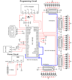
The personal radar system utilizes the PIC microcontroller PIC18F452 as a hobby project. The attached circuit diagram of the radar may appear simple; however, careful analysis of the PIC18F452 radar circuit is necessary to prevent damage. This personal radar...

Utilize a PIC Microcontroller to Control a Hobby Servo. This guide outlines the process of incorporating hobby servos, typically found in remote-controlled airplanes, cars, and similar devices. To implement the control of a hobby servo using a PIC microcontroller, the...
This project enables a PIC microcontroller to play audio PCM sounds using PWM modulation. Pulse-code modulation (PCM) is a digital representation of audio signals. The project utilizes a PIC microcontroller, which is programmed to generate audio signals through pulse-width modulation...

The I2C PIC Interfacing Tutorial circuit is relatively straightforward; however, it requires careful verification to ensure that all connections are correct before initial operation. The primary components utilized in this circuit include the PIC18F452 microcontroller, the 24LC02B EEPROM, and...
To achieve this project, the initial concept involves sampling an input using an Analog-to-Digital Converter (ADC) at consistent time intervals and subsequently displaying the waveform on a graphic LCD. Adjusting the time scale can be done by modifying the...
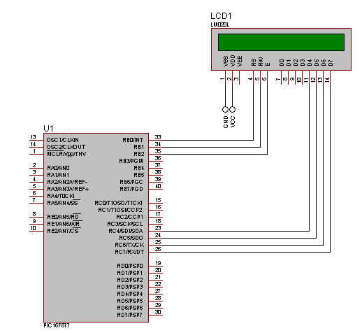
When using an LCD in 4-bit mode, data must be sent twice, whereas in 8-bit mode, it is sent only once. This increases the workload on the microcontroller when interfacing with the LCD. If the microcontroller is handling only...