
Simple Pulse Generator by IC 555 Timer

The astable oscillator circuit utilizing the NE555 timer IC serves as a versatile pulse generator, producing a continuous square wave output. This circuit is commonly employed in applications such as clock pulses, tone generation, and LED flashers. The NE555 timer operates in the astable mode, which means it continuously switches between its high and low output states without requiring any external triggering.
In this configuration, the circuit consists of the NE555 timer, two resistors (R1 and R2), and a capacitor (C1). The resistors define the charge and discharge times of the timing capacitor, ultimately determining the frequency and duty cycle of the output signal. The output frequency (f) can be calculated using the formula:
f = 1.44 / ((R1 + 2 * R2) * C1)
Where:
- R1 is the resistor connected between VCC and the discharge pin (Pin 7).
- R2 is the resistor connected between the discharge pin (Pin 7) and the threshold pin (Pin 6) as well as the trigger pin (Pin 2).
- C1 is the capacitor connected between the threshold pin (Pin 6) and ground.
The duty cycle (D) of the output signal can be calculated using the formula:
D = (R2 / (R1 + 2 * R2)) * 100%
This provides insight into the proportion of time the output signal remains high versus low.
To construct the circuit, connect the NE555 timer according to the standard astable configuration. Ensure that the power supply voltage (VCC) is within the operational range specified in the NE555 datasheet, typically between 4.5V and 15V. The output can be taken from Pin 3, which provides a square wave signal suitable for driving various loads or interfacing with other digital circuits.
In summary, the NE555 timer configured as an astable oscillator is an essential building block in electronics, capable of generating precise timing signals for a wide range of applications. Proper selection of resistor and capacitor values allows for customization of the output frequency and duty cycle to meet specific needs.This is a simple pulse generator circuit or standard astable oscillator circuit for IC 555 timer,NE555N IC. Use for.. 🔗 External reference
Related Circuits
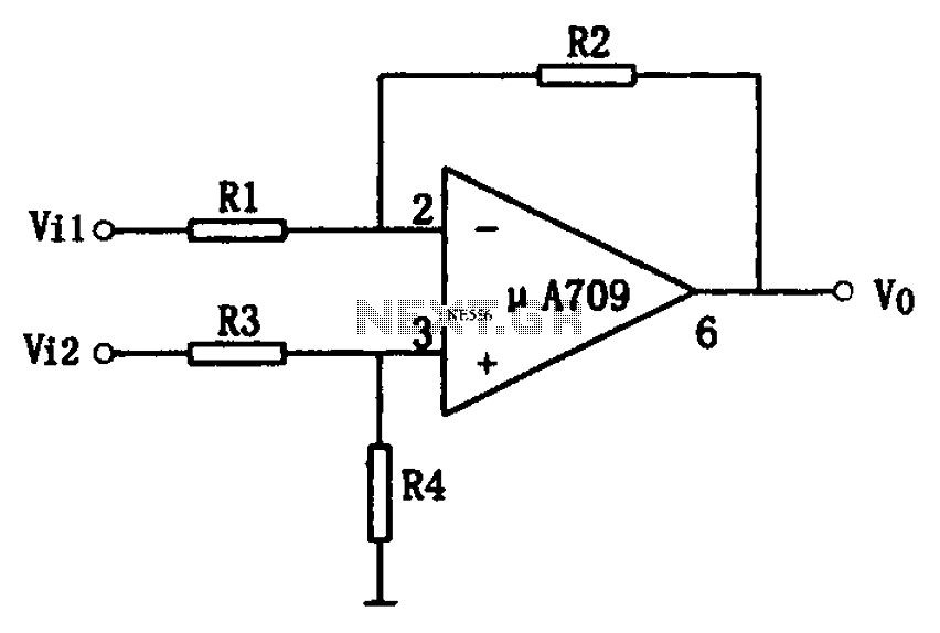
The simple differential amplifier circuit consists of two input signals, Vi1 and Vi2, which are connected through resistors R1, R3, and R4, forming a voltage divider circuit at the op-amp input. Vi1 is applied to the inverting input of...
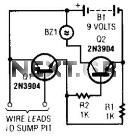
A common collector amplifier drives a 2N3904 switch to sound alarm BZ1. The wire leads to a water sensor or sump pit, level switch, etc. It is used to allow the alarm to operate and be mounted in a...
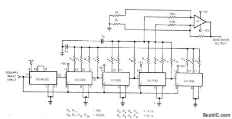
Frequency changes produced in a Colpitts oscillator by a metal object near the tank coil are indicated by a 565 PLL connected as a frequency meter. The oscillator frequency increases when the search coil is brought near a non-ferrous...
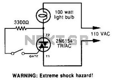
A triac can be utilized as a line-operated AC power switch that directly controls lamps, heaters, or motors. A brief current pulse into the gate activates the triac, and it remains on until the main current reverses. A triac, or...
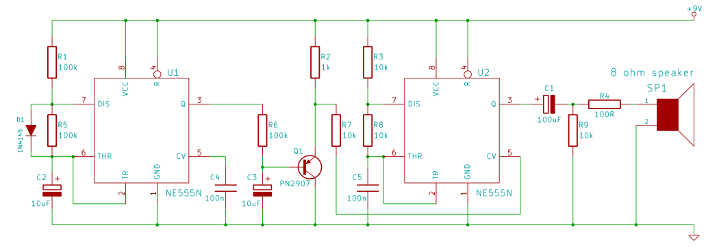
This tutorial outlines the construction of a wailing siren that produces a tone with varying pitch. The circuit incorporates two 555 integrated circuits (ICs) and a loudspeaker. The wailing siren circuit is designed to create an audio effect that simulates...
555 Timer Sound Effects Videos 1. This project involves creating a light theremin using a 555 timer. It is suitable for spooky Halloween effects. 3. A film countdown timer is included. 4. A UHD chessboard timer is also featured....