
Politely welcoming electronic doorbell

The electronic doorbell circuit operates by utilizing a trigger control mechanism that activates the audio output when the doorbell button is pressed. The button (S) serves as the primary input, which, when engaged, completes the circuit. This action can also be influenced by magnetic switches (SA) that may be employed to enhance the circuit's functionality, allowing for additional activation methods.
Transistors (V4 and V5) function as amplifiers and switches in the circuit, controlling the flow of current based on the input received from the doorbell button and magnetic switches. The resistors (R3, R4, and R6) are used to limit current and set appropriate voltage levels for the transistors to operate efficiently. Diodes (VD2 and VD3) are included to prevent reverse polarity and protect sensitive components from voltage spikes.
The audio amplifier output circuit is responsible for amplifying the sound generated by the music circuit, which produces the welcoming tones when the doorbell is activated. The voice delay control circuit adds a feature that allows for a brief pause before the sound is emitted, enhancing the overall user experience by providing a more refined auditory response.
This circuit design emphasizes reliability and user-friendliness, making it suitable for various residential applications. The combination of these components ensures that the electronic doorbell functions effectively, delivering a pleasant sound to greet visitors.The politely welcoming electronic doorbell circuit is composed of the trigger control circuit, audio amplifier output circuit, music circuit, voice delay control circuit, and it is shown in Figure 3-122. Trigger control circuit is composed of the doorbell button S, magnetic switches SA, transistors V4, V5, resistors R3, R4, R6, diodes VD2, VD3, and capacitor..
🔗 External reference
Related Circuits
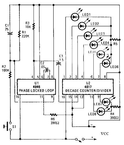
An electronic circuit for a roulette wheel can be constructed using a 4046 Phase-Locked Loop (PLL) that includes a Voltage Controlled Oscillator (VCO), two phase comparators, a source follower, and a Zener diode to generate a low-frequency pulsed output...
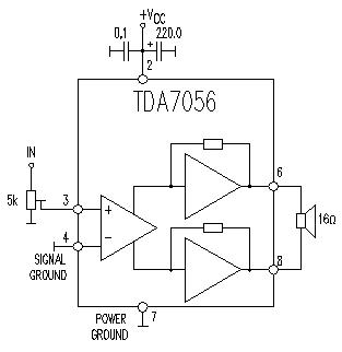
This TDA7056 power audio amplifier circuit diagram project is designed to deliver a maximum output power of 1 watt into an 8-ohm load when powered by a 6-volt supply, or a maximum output power of 3 watts into a...

The electronic watchdog circuit functions similarly to a traditional guard dog, monitoring a 10-meter area around a door. When someone enters this monitored zone, the circuit emits a realistic barking sound. This sound can be sustained for 10 seconds,...

The input capacitor is used for low-frequency cut-off, with a standard value of 0.1 µF, resulting in a cut-off frequency of approximately 16 Hz. The input capacitor plays a critical role in electronic circuits, particularly in signal processing and audio...

This lie detector circuit provides two readings: one for difficult questions and another for the subject's general emotional state. Two flexible, uninsulated wires wrapped around the fingers or wrist can serve as electrodes. Each change in resistance, and consequently...
The digital lock shown below uses 4 common logic ICs to allow controlling a relay by entering a 4 digit number on a keypad. The first 4 outputs from the CD4017 decade counter (pins 3,2,4,7) are gated together with...