
positive negative probe with ic 555

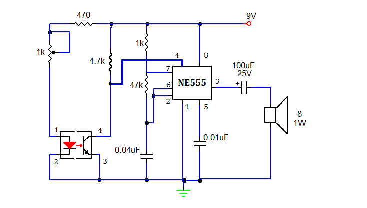
This circuit employs an integrated circuit (IC) 555 configured in a comparator mode to differentiate between positive and negative voltages. The circuit's design is straightforward, comprising the IC 555, two light-emitting diodes (LEDs) for visual indication, and a protective diode (1N4002).
The power supply for the circuit is connected across the power pins of the IC, ensuring that it operates within the specified voltage range of 5 to 15 volts. The two LEDs serve as indicators: the red LED signifies the presence of a positive voltage, while the green LED indicates a negative voltage. The operation of the LEDs is controlled by the output of the IC 555, which changes state based on the voltage level detected at its input pin.
When a positive voltage is applied to pin 3 of the IC, the output goes high, activating the red LED and illuminating it. Simultaneously, the green LED is turned off. This visual feedback allows the user to easily ascertain the polarity of the voltage at the test point. On the other hand, when a negative voltage is applied, the output of the IC changes state, turning off the red LED and illuminating the green LED.
The inclusion of the 1N4002 diode is crucial for protecting the circuit from potential damage due to incorrect polarity connections. This diode ensures that the current flows in the correct direction, safeguarding sensitive components within the circuit.
Overall, this circuit is a practical solution for quickly identifying voltage polarity in automotive or motorcycle applications, providing an efficient and low-cost method for users to check voltage levels safely. The simplicity of the design makes it accessible for both novice and experienced electronics enthusiasts.With this circuit you can can check that which dot of the circuit is Positive Volt or Negative Volt which. This cheap circuit uses the a little component is will appropriate apply with an automobile or motorcycle.
This circuit works during Voltage between 5-15V. When build volt supply of circuit LED 2 pcs. of stick bright but enough check meet Pos itive Volt make at pin 3 of IC 555 liberate Negative volt come out cause Red LED stick bright next but Green LED switch off down replace. But when check meet Negative Volt make Red LED switch off but Green LED stick bright replace yes. The Diode 1N4002 be formed protect turning pole electricity over. The detail is other, see in the circuit please sir. 🔗 External reference
Related Circuits
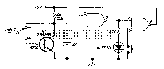
There are two switches: a memory disable switch and a pulse polarity switch. The memory disable switch is a push-button that resets the memory to a low state when pressed. The pulse polarity switch is a toggle switch that...
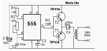
This 12V power inverter circuit can be utilized to supply power to small devices that require 240 volts. It is particularly beneficial when there is a need to operate equipment designed for 240 volts. The 12V power inverter circuit is...
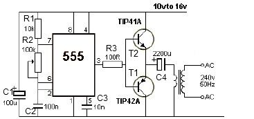
12V power inverter circuit utilizing a 555 timer for an electronic project. The 12V power inverter circuit is designed to convert a DC voltage of 12 volts into an AC voltage suitable for powering small electronic devices. The core component...
This document presents a simple smoke sensing alarm circuit utilizing a 555 timer. The circuit is designed to detect smoke and trigger an alarm when the air is contaminated. The components employed in this design include an astable multivibrator...
The controller circuit illustrated in Figure 15-24 consists of a switch-type Hall integrated circuit DN838 and an astable multivibrator, which is based on the 555 timer IC. This circuit is suitable for various applications, including automatic door opening, delay...
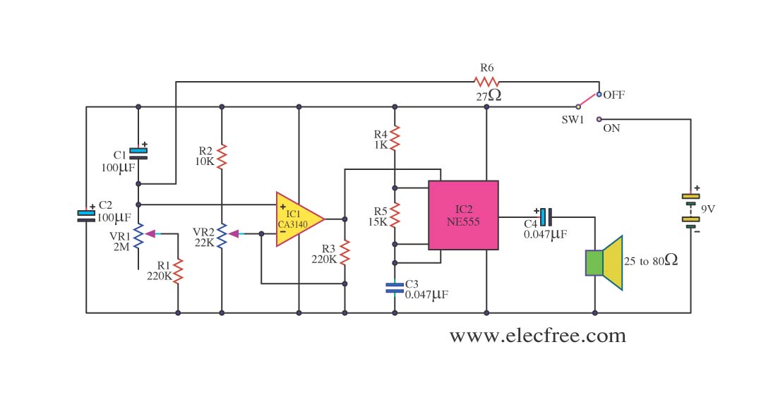
This circuit sets the time using a simple model that can accurately maintain the time over extended periods. It employs the CA3140 integrated circuit for its functionality. The circuit utilizes the CA3140 operational amplifier, which is known for its high...