
Charging circuit diagram personal work
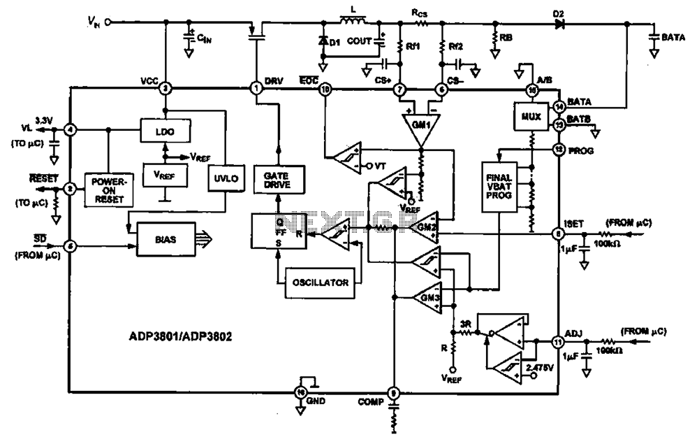
The ADP3801/3802 is a highly integrated battery charger controller designed for Li-ion and Li-polymer batteries. The charging circuit typically consists of several key components including the battery management IC (ADP3801/3802), power MOSFETs for switching, resistors for voltage sensing, capacitors for filtering, and a diode for reverse current protection.
The operation begins when the input voltage is applied to the circuit. The ADP3801/3802 monitors the battery voltage and determines the appropriate charging mode. This device supports multiple charging phases: preconditioning, constant current (CC), and constant voltage (CV). During preconditioning, if the battery voltage is below a certain threshold, a low charging current is applied to safely charge the battery. Once the battery reaches a predefined voltage level, the circuit transitions to the constant current mode, where a higher charging current is supplied until the battery voltage approaches the set limit.
As the battery voltage reaches the target voltage, the circuit shifts to the constant voltage mode, where the charging current gradually decreases until it reaches a minimal level, indicating that the battery is fully charged. The ADP3801/3802 also includes features such as temperature monitoring and charge termination to prevent overcharging and ensure battery safety.
The schematic layout should include the power supply input, the ADP3801/3802 IC, the necessary passive components (resistors, capacitors), and the battery connection. Proper layout considerations, such as minimizing loop areas for high-frequency signals and ensuring adequate thermal management for the MOSFETs, are critical for reliable operation. The overall design should adhere to best practices for PCB design to optimize performance and efficiency in charging applications. Charging circuit diagram personal work For the operating principle ADP3801/3802 charging circuit.
Related Circuits
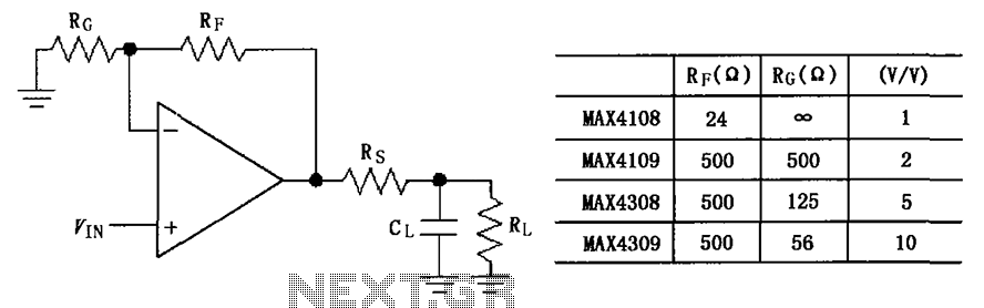
The circuit depicted in the figure employs the MAX4108/4109/4308/4309 operational amplifiers with a capacitive load driving circuit isolation resistor (Rs). While the MAX4108/4109/4308/4309 exhibits excellent AC characteristics, it is not optimized for driving high-load electrical resistances. A significant reactive...
The schematic diagram of the MS Decoder may appear complex, but it is relatively straightforward. Initially, both the Mid and Side signals are buffered using unity gain inverting buffers, which are constructed around IC1b and IC2b. This buffering serves...
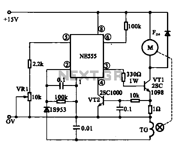
The Miniature DC Motor Speed Control circuit is designed to maintain a steady speed for micro motors, as illustrated in Figure 8-32. The circuit utilizes a voltage feedback mechanism suitable for applications such as tape recording machines that employ...
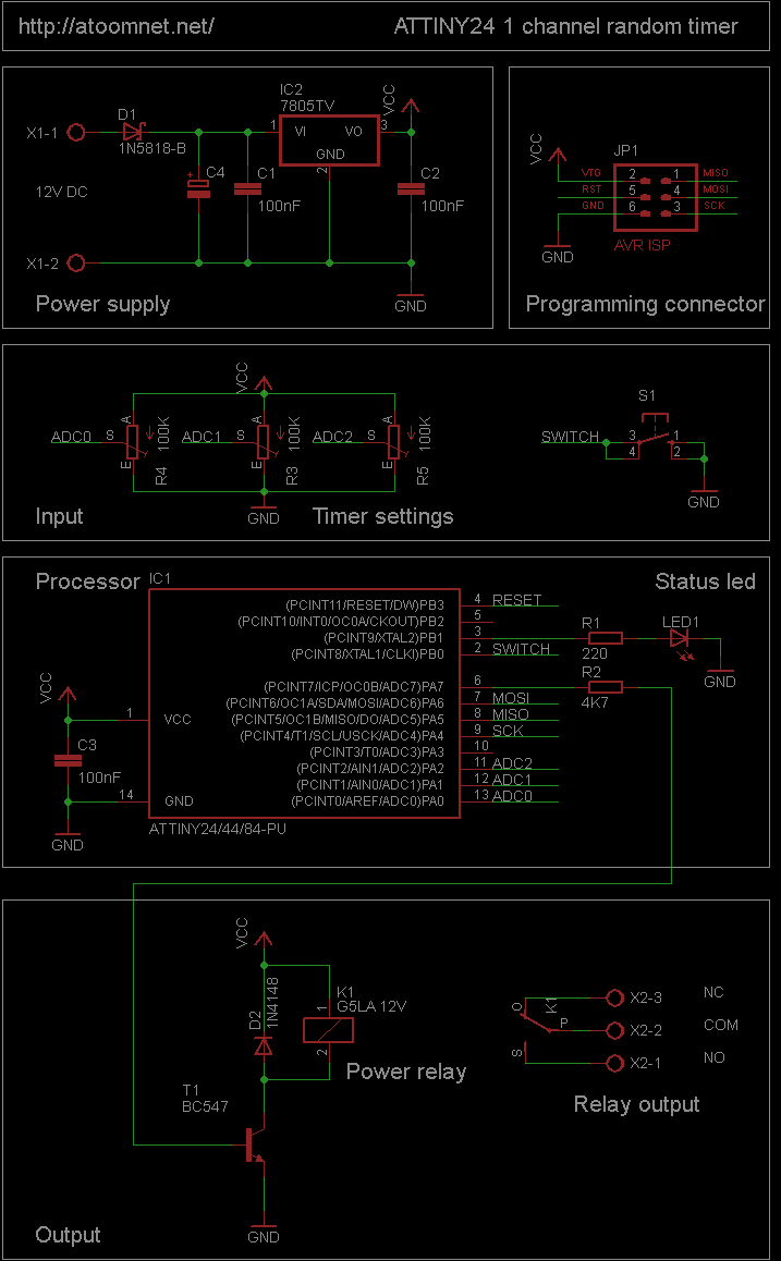
This random timer circuit is based on an Atmel ATTINY24 AVR driving one power relay. It can be used to switch on and off other circuits randomly. For instance, in a model railroad setup, this circuit can activate and...

Digital Command Control (DCC) provides significant advantages over traditional DC analog control systems, primarily due to its simplified wiring. DCC enables the individual control of multiple locomotives on the layout without requiring electrical isolation of track sections. The main...
This circuit is a modified Hartley oscillator that incorporates additional components. It utilizes a small audio transformer, specifically the LT700 model. The primary winding is center-tapped with an impedance of 1 kΩ at 1 kHz, while the secondary winding...