
power supply adjustable 0v 30v dc2a

The described circuit is an effective linear voltage regulator that utilizes the LM723 integrated circuit, known for its reliability and versatility in power supply applications. The LM723 serves as the primary control element, maintaining a stable output voltage by adjusting the base current of the power transistor Q1, which in this case is a 2N3055. This NPN transistor is capable of handling high currents, making it suitable for applications requiring significant power output.
The potentiometer R1 plays a critical role in setting the output voltage. By adjusting R1, the user can vary the feedback voltage to the LM723, which in turn adjusts the base voltage of the 2N3055, allowing for precise control over the output voltage within the specified range. It is important to note that the output voltage is limited by the transformer TR1's specifications. A transformer capable of supplying adequate current is necessary to achieve the desired 30V output; inadequate current supply will result in a lower output voltage, typically around 26V.
The selection of a proper heatsink for the 2N3055 is crucial, as this transistor will dissipate significant heat during operation, especially under high load conditions. Without adequate thermal management, the transistor may overheat, leading to thermal shutdown or permanent damage. Therefore, a heatsink with appropriate thermal conductivity and surface area should be employed to maintain safe operating temperatures.
In addition to the heatsink, the choice of potentiometer R1 is also important. A high-quality potentiometer will ensure stable and reliable voltage adjustments, minimizing noise and improving overall circuit performance. The circuit may also benefit from the inclusion of bypass capacitors near the LM723 and the power transistor to filter out any high-frequency noise and improve transient response.
Overall, this regulated power supply circuit is a practical solution for various electronic projects requiring adjustable DC voltage, offering simplicity in design while maintaining the capability to deliver stable output under varying load conditions.It is a simple circuit regulated power supply, based on the known LM 723, that drive a transistor Q1 [2N3055]. The regulation of voltage, of expense becomes with potentiometer R1 from 0v-30v DC roughly. In order to we achieve 30 V, will should the transformer of supply TR1, it gives all the current that it asks the load, differently the output voltage it will be found in the levels of 26 V roughly.
Essential is the use of a good heatsink for transistor Q1, as well as good quality of potentiometer in the place of R1.. 🔗 External reference
Related Circuits
T1 steps down AC voltage from 115VAC (or 220VAC) to about 8VAC and is then rectified via bridge rectifier BR1 to about 11.52Vdc. C1 filters off the AC ripple. If you find the circuit output too noisy add another...
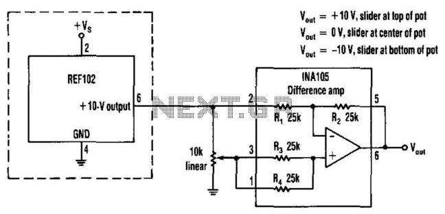
This circuit provides a precision voltage source that can be adjusted to produce zero, positive, and negative voltages, eliminating the need to reverse connections on the power supply. It allows for achieving exactly 0 V without any offset. The...
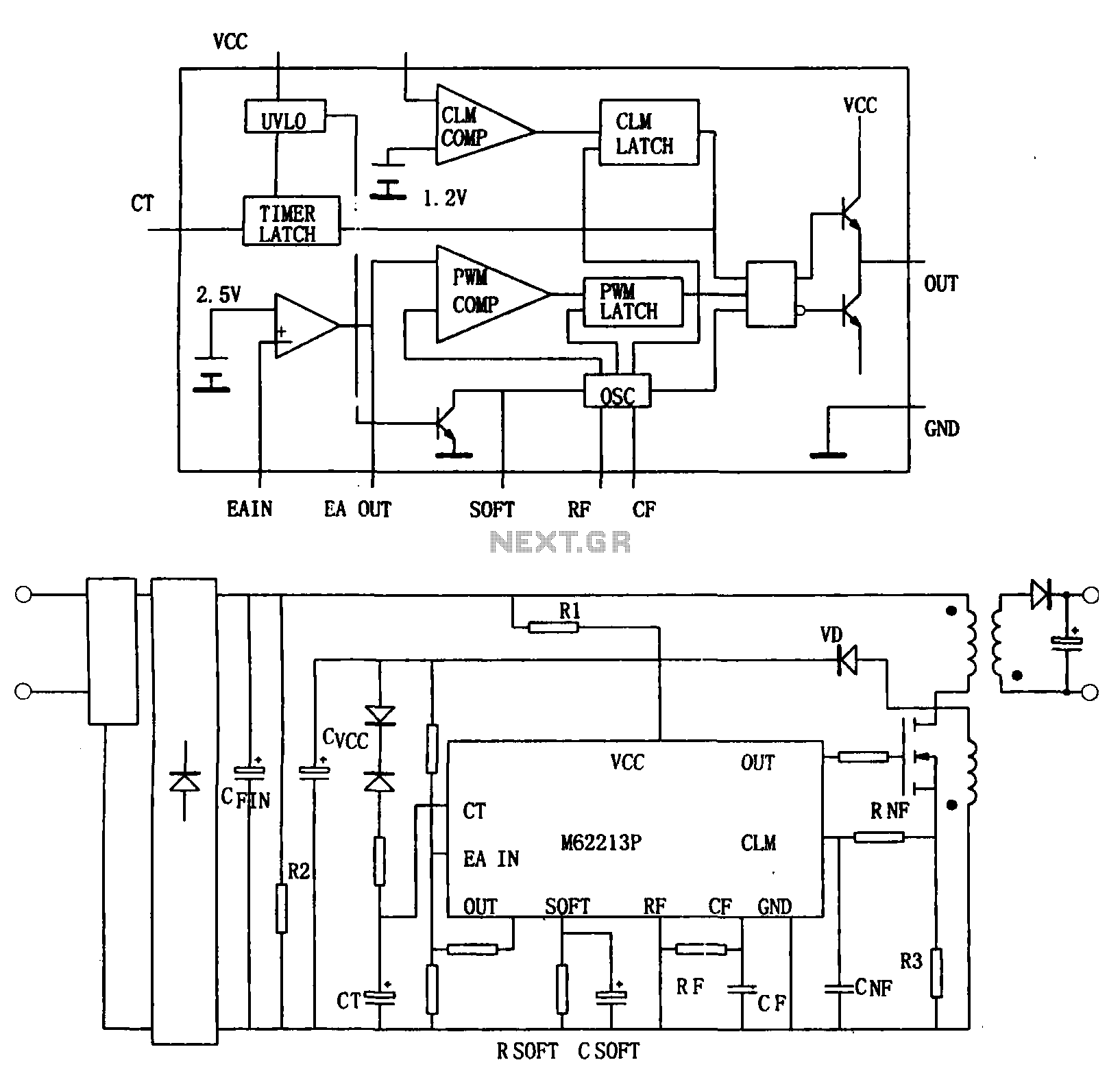
Figure (a) illustrates a block diagram of the internal architecture of the M62213FP, which is a high-speed switching power supply controller. This device includes an oscillator, PWM comparator, error amplifier, output circuit, over-voltage protection, timing latch circuit, over-current protection...
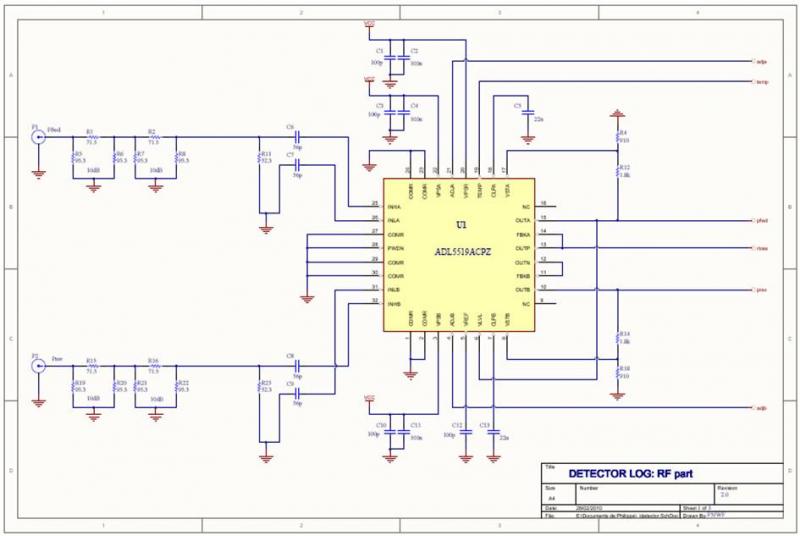
The ADL5519 is particularly focused on bandwidth, specified up to 8 GHz, though it remains usable at 10 GHz with reduced dynamic range. It features two channels, allowing for the measurement of power transmitted to the antenna and the...
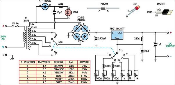
The battery-operated toy has malfunctioned, necessitating repair. Upon disassembly, the battery compartment may be disconnected from the circuitry, or the batteries might be depleted. A solution is to implement a switchable power supply designed to replace one to six...
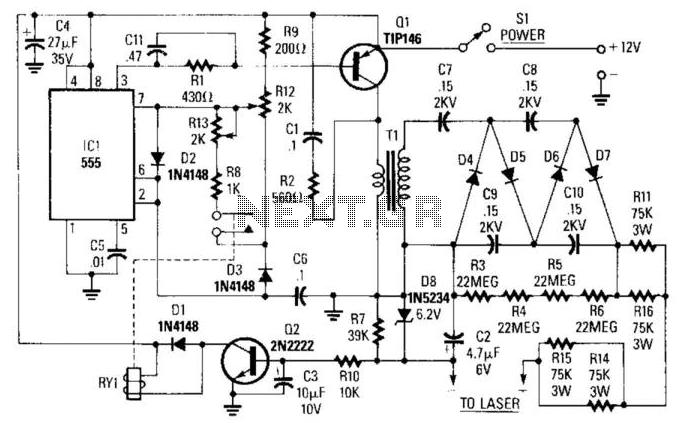
IC1 is a 555 timer operating at approximately 16 kHz. This integrated circuit drives Q1, a TIP146 transistor, which generates a 12-V square wave across the primary winding of transformer T1. This results in an output voltage ranging from...