
Pulse Voltage Multiplier

There is no free lunch with this circuit. If the pulse is initiated before the 150k AND 100K resistors charge the 100 uf capacitor sufficiently (60k x 100 uf = 6 seconds), the output voltage will be lower than intended. The charge time of the circuit can be decreased by reducing the values of the capacitors, the output 100 uf capacitor having the most effect because of the high resistance charge path. Reducing the size of the capacitors will make the output pulse droop more quickly.
It should be noted that this circuit also makes a 0 to 10 volt pulse, which appears on the collector of the transistor. If a 0 to 10 volt pulse is desired, the circuitry to the right of the transistor's base resistor may be omitted.
This circuit functions as a voltage multiplier utilizing a switching transistor, diodes, and capacitors to achieve its output without requiring a continuous pulse stream. The transistor acts as a switch, controlled by the input signal, while the output voltage is determined by a resistor divider network composed of 100k and 150k resistors. This configuration allows for an additional 2 volts to be added to the 10-volt pulse present on the transistor's collector, resulting in a maximum output voltage of 12 volts.
In the design, the left-side diode can often be removed to simplify the circuit, with the 1k resistor being replaced by a 100k resistor. This modification, however, leads to a quicker voltage droop across the 100 µF capacitor, as it now discharges into both the 100k resistor and the load. The circuit's performance is contingent on the proper charging of the capacitors; specifically, if the pulse is applied before the resistors sufficiently charge the capacitor, the output voltage may not reach the desired level. The time constant for charging the capacitor is dictated by the product of the resistance and capacitance values (60k x 100 µF = 6 seconds).
To enhance performance, reducing the capacitance values can expedite the charging process, particularly for the output capacitor, which has the most significant impact due to its high resistance charging path. However, this will also lead to a more rapid droop of the output pulse voltage.
The circuit is capable of generating a 0 to 10-volt pulse at the collector of the transistor. For applications requiring this specific output, the components situated to the right of the transistor's base resistor may be excluded, streamlining the design further. Overall, this circuit is a practical solution for applications needing pulse voltage control without the need for continuous pulse input. It still uses a transistor to do some switching, and it still needs a pair of diodes and capacitors, as would be used in a conventional multiplier, but it doesn't require a steady stream of pulses and the output voltage is set by a resistor divider as the 100k and 150k resistors make 2 volts that are added to the 10 volt pulse on the transistors' collector. What it doesn't need is a steady stream of pulses to keep the output voltage pumped up all the time. The basic multiplier cell was inspired by a discussion I had with a well know laser scientist, Mr. Christoph Krah, about laser triggering circuits. After I finished this circuit, I sent it to Mr. Krah to get his opinion of how this circuit related to some of those we discussed years ago. For many of applications, the diode on the left side can be omitted and the 1k resistor changed to 100k.. This simplifies the circuit at the cost of slightly increasing the rate of droop of the voltage across the first 100 uf capacitor since it will discharge into the 100k resistor as well as driving the base resistor for the transistor and driving the load and 100k/150k voltage divider.
There is no free lunch with this circuit. If the pulse is initiated before the 150k AND 100K resistors charge the 100 uf capacitor sufficiently (60k x 100 uf = 6 seconds), the output voltage will be lower than intended. The charge time of the circuit can be decreased by reducing the values of the capacitors, the output 100 uf capacitor having the most effect because of the high resistance charge path.
Reducing the size of the capacitors will make the output pulse droop more quickly. It should be noted that this circuit also makes a 0 to 10 volt pulse, which appears on the collector of the transistor. If a 0 to 10 volt pulse is desired, the circuitry to the right of the transistor's base resistor may be omitted.
🔗 External reference
Related Circuits
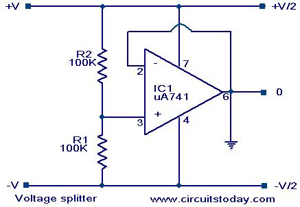
Voltage splitter using op-amp uA741 IC, circuit diagram, working, description. The voltage splitter circuit utilizing the uA741 operational amplifier (op-amp) is designed to provide a stable output voltage that is a fraction of the input voltage. The uA741 is a...
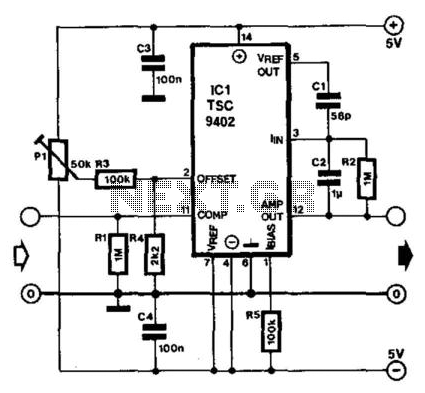
Teledyne Semiconductor's Type TSC9402 is a versatile integrated circuit (IC) capable of converting voltage to frequency and frequency to voltage. It is well-suited for use as an add-on unit for measuring frequencies with a multimeter, requiring only a few...
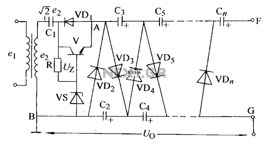
The circuit is an adjustable output voltage regulator type rectifier. It allows for obtaining peak voltage at odd multiples when the output voltage is taken from the circuit feedback (FB). Additionally, the lower point of the capacitor (CB) can...
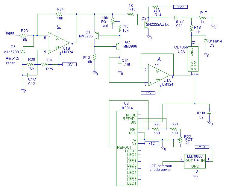
The schematic for the pulse width monitor features a transistor current source that charges capacitor C10, functioning as an integrator. The capacitor charges, causing the voltage across it to increase linearly for the duration that the injector remains energized....
This circuit utilizes a dual-timer NE556 to generate 1Hz pulses spaced 5 seconds apart, with the option for manual or automatic operation. The NE556 integrated circuit (IC) consists of two independent timers. The NE556 timer is a versatile device that...
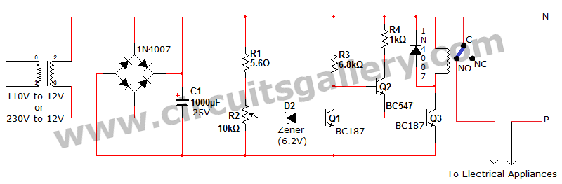
Voltage fluctuation is a significant concern in residential settings. For various reasons, the supply voltage may exceed 110V or 230V. This excessive voltage can potentially damage household electrical devices. An effective solution for electrical protection is the implementation of...