
pulse width modulated (PWM) controller for high current
 controller for high current")
The circuit utilizes a 555 timer configured in monostable mode, which generates a single output pulse in response to a trigger signal. The pulse duration is controlled by an RC timing network comprising a resistor (the potentiometer) and a capacitor (0.039 µF). The duty cycle can be adjusted by varying the resistance of the potentiometer, which alters the duration of the output pulse. A lower duty cycle results in shorter output pulses, thereby reducing the average voltage supplied to the motor and consequently slowing it down. The use of two TIP120 transistors in parallel enhances the current handling capacity, allowing for efficient motor control while minimizing the risk of overheating. The cascade configuration of the TIP120s amplifies the current capability further, ensuring that the 555 timer operates within safe limits. The choice of a linear slide potentiometer allows for intuitive control of motor speed, translating the rotary motion of the servo into a linear adjustment for precise speed regulation. The overall design is compact, suitable for limited space applications such as on a boat, and effectively meets the operational requirements of the motor control system.The second 555 timer was configured as a monostable circuit, commonly referred to as a one shot since an output pulse only occurs if there is a trigger on the input. When this timer is triggered, the potentiometer in the RC timing network allows the output duty cycle to vary, which determines how long each output pulse is high.
As the output high pulse gets shorter, less current will flow in the motor causing the motor to slow down. Figures 2 and 3 show a high and low duty cycle pulse for the circuit, respectively, captured on an oscilloscope. The top graph of each figure is the output pulse, while the bottom graph is the input into the monostable timer.
If the duty cycle is brought down to zero percent, there will no longer be a high part of each pulse, therefore no current will flow. The capacitor value was chosen to be 0. 039uF. I wanted a minimum RPM of 500 for the motor, so the potentiometer was chosen accordingly. Equation 3 shows how the value of the potentiometer was chosen. The maximum resistance was calculated as 46k ohms, therefore, I used a standard value 50k precision audio potentiometer.
This would assure that I could achieve a low RPM on the motor. Position of the potentiometer can be adjusted using the rotary to linear action of the servo system of the radio. For this design, a linear slide potentiometer was chosen to accommodate this rotary to linear action of the servo system.
As mentioned, the motor can draw several amps, requiring a robust transistor to provide the current control in the circuit. Based on their current handling capabilities, TIP120 BJT transistors were chosen as the output stage to drive the motor.
Two TIP120 ’s were wired in parallel to distribute the current load and keep either transistor from running too hot. Also, space is at a premium on the boat, therefore the transistor had to operate with little or no heatsinking.
After testing showed that the transistors were pulling too much current directly from the monostable 555 timer output and causing premature failures, an additional TIP120 was incorporated in a cascade arrangement with the output transistors to produce a larger gain. The output of the 555 timer has a maximum current output of 200 mA and Equation 4 shows how there could be an overcurrent condition, based on a start up current of 20 amps and a typical gain of approximately 100.
If the gain is 100 and the motor requires 20 amps, the 555 timer would have to supply about 200 mA, demanding nearly the maximum current from the timer and causing it to overheat and burn up. By saturating the first stage of the cascade with the output from the monostable 555 timer and running the emitter of the first transistor into the bases of the output transistors, the gain on the output stage was increased by approximately 100, lowering the current demand of the timer to 2 mA.
The operating voltage for the system is 7. 2 volts. This voltage was chosen because this is the voltage of the motor battery pack. The 555 timers can run on +5 to +18 volts so the battery pack can be used to run the speed controller as well with no voltage regulation. The circuit schematic is shown below in Figure 3 as designed and built. The circuit is working correctly, the way it was designed, but the speed controlling potentiometer is slightly nonlinear.
The output pulse falls low and the transistors turn off completely when the slide is all the way down so the motor will not draw current when idle. However, the very top end of the slide does not increase the speed past a certain point. For this design and motor, though, the controller works fine. 🔗 External reference
Related Circuits
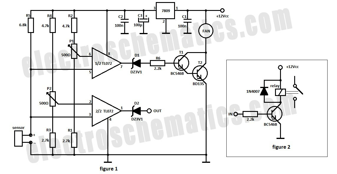
The automatic fan controller circuit depicted in the schematic features two comparators with distinct triggering points that can be adjusted independently. LM135 or... The automatic fan controller circuit is designed to regulate fan operation based on temperature variations. It employs...
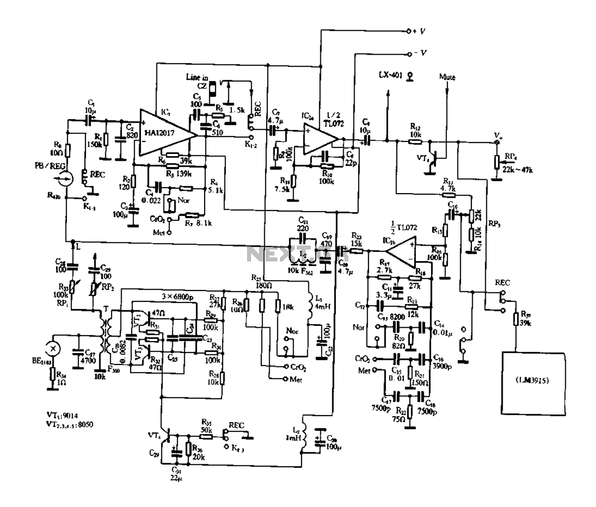
Figure 3-17 illustrates a pre-equalizer amplifier with sound recording capabilities, featuring the following characteristics: (1) The circuit does not utilize a conventional mechanical switch circuit; instead, it employs fully enclosed electromagnetic relays. This design allows for a core and...
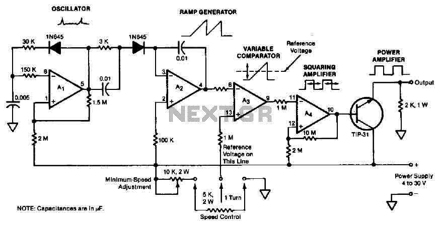
The quad operational amplifier circuit provides a pulse width modulation control ranging from 0 to 100 percent. The controller utilizes an LM3900 and operates with a single supply voltage between 4 to 30 V. A 1 kHz oscillator amplifier,...
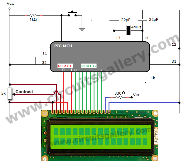
The process of interfacing an LCD (Liquid Crystal Display) module with a PIC microcontroller involves understanding the nature of LCDs as passive components that modify light rather than generate it. LCDs are specifically designed for use with microcontrollers and...
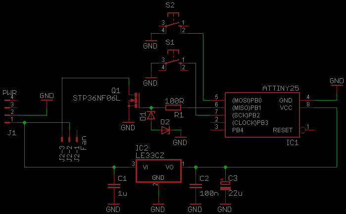
This document serves as a continuation of the previous work on PWM controllers utilizing 555 timers. The new design incorporates microcontrollers and MOSFETs in place of the 555 integrated circuits and transistors. Two versions have been developed: one equipped...
This simple circuit generates narrow pulses at a frequency of approximately 700-800 Hz. The pulses, which contain harmonics extending into the MHz range, can be injected into audio or radio-frequency stages of amplifiers and receivers for testing purposes. A...