
relay interfacing with fpga universal development board

The Universal Development Board is designed to facilitate the interfacing of external 5V relays, enabling users to control high-power devices through low-power FPGA I/O lines. The core of the relay control mechanism is the ULN2803, a high-voltage, high-current Darlington transistor array. This component allows the FPGA to drive multiple relays simultaneously without exceeding the current limits of the FPGA's output pins.
In this setup, the ULN2803 connects directly to the FPGA's I/O lines, with each output pin of the ULN2803 linked to an individual relay module. The relays act as electromechanical switches, enabling the control of larger loads such as motors, lights, or other high-voltage devices. The inclusion of a PTB connector allows for an external power supply to be connected to the system, ensuring that the relays receive adequate power for operation, especially when controlling devices that require more current than the FPGA can provide.
Additionally, the board features signal LEDs for each relay, providing a visual indication of the relay's status. These LEDs illuminate when the corresponding relay is activated, allowing for quick verification of the system's operational state. This feature enhances troubleshooting and monitoring capabilities during development and testing phases.
Overall, the Universal Development Board is a versatile platform for developing and testing applications that require relay control, offering robust interfacing capabilities and user-friendly indicators for system status.The Universal Development Board has external 5v Relay interfacing, indicated as in Figure. ULN2803 is used as a driver for FPGA I/O lines, drivers output connected to relay modules. PTB connector provided for external power supply if needed. Signal LEDs for each relay help you to easy determine current relay state. 🔗 External reference
Related Circuits

This combination sync stripper and universal video interface can solve various problems, including interfacing Super Nintendo with other devices, video overlay, and locking TV frames for scopes. Kits, fully tested units, and custom cable assemblies are available through Redmond...
The circuit operates continuously, turning on and off. It utilizes the widely recognized NE555 timer IC, known for its versatility in various electronic applications. In this configuration, the IC is set up as an astable multivibrator. A 12-volt relay...

Efforts were made to minimize the number of wire jumpers on this board, but space constraints arose due to the integration of the microcontroller and motor driver on a single board. The design would have been cleaner without the...
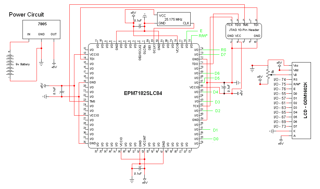
The schematic for this project is a modified version of the CPLD development board schematic. Several new components have been added for this project, and the completed schematic is presented below. The primary components in the schematic include the...
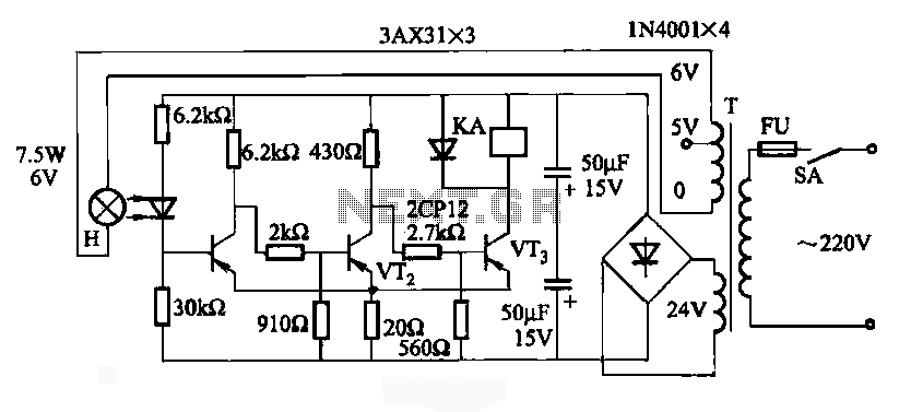
JG series of photoelectric relay circuit. To ensure reliable operation, a Schmitt trigger circuit has been incorporated. These circuits function similarly; when light strikes the photosensitive component, its internal resistance decreases, activating the transistor VT and subsequently energizing the...
In this circuit, the 555 Timer IC is configured as an astable multivibrator, and a 12-volt relay is operated through pin 3 of the IC. The IC generates continuous pulses at pin 3, which activate and deactivate the relay,...