
LEDs or Lamps Sequencers

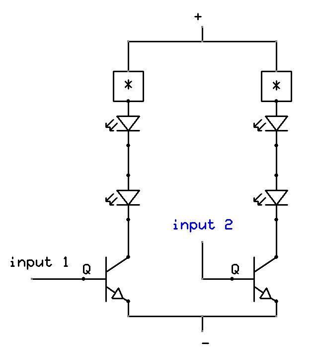
This circuit functions as a sequential LED or lamp controller, allowing for a customizable number of illuminating devices arranged in a loop configuration. Each device operates on its own circuit, providing flexibility in design. The circuit can be visualized as a series of interconnected stages, where each stage corresponds to an individual LED or lamp. The output of the last stage feeds back into the input of the first stage, creating a continuous loop that enhances the visual effect of sequential illumination.
The pushbutton P1 serves a dual purpose: it initiates the lighting sequence upon power-up and allows for adjustments during operation. The requirement to hold P1 until a specific LED or lamp lights up ensures that the user can select which device will be the starting point for the sequence. This feature is particularly useful in setups where multiple devices are present, as it provides control over which device is illuminated first.
The sequencer operates by cycling through the stages based on a predetermined timing mechanism, which may involve resistors and capacitors that define the time delay between each stage's illumination. When P1 is pressed briefly during the operation, it introduces variability into the sequence, allowing for creative lighting patterns based on the number of stages configured.
For applications involving higher current lamps, the recommendation to replace standard BC337 transistors with Darlington transistors is crucial for ensuring reliable operation. Darlington transistors provide higher current gain, making them suitable for driving devices that require more power. The transition from older germanium technology to modern silicon-based components and the adoption of LEDs signifies advancements in efficiency, reliability, and overall performance of the circuit.
In summary, this circuit design offers an innovative and versatile solution for sequential lighting applications, accommodating a wide range of configurations and enhancing user control over the illumination sequence. The incorporation of modern components further improves its functionality and reliability, making it suitable for contemporary lighting projects.The purpose of this circuit was to create a ring in which LEDs or Lamps illuminate sequentially. Its main feature is a high versatility: you can build a loop containing any number of LEDs or Lamps, as each illuminating device has its own small circuit. The diagrams show three-stage circuits for simplicity: you can add an unlimited number of stages (shown in dashed boxes), provided the last stage output was returned to the first stage input, as shown. P1 pushbutton purpose is to allow a sure start of the sequence at power-on but, when a high number of stages is used, it also allows illumination of more than one LED or Lamp at a time, e.
g. one device illuminated and three out and so on. After power-on, P1 should be held closed until only the LED or Lamp related to the module to which the pushbutton is connected remains steady illuminated. When P1 is released the sequencer starts: if P1 is pushed briefly after the sequence is started, several types of sequence can be obtained, depending from the total number of stages.
If you intend to use lamps drawing more than 400mA current, BC337 transistors should be substituted by Darlington types like BD677, BD679, BD681, 2N6037, 2N6038, 2N6039 etc. A similar design appeared in print about forty years ago. It used germanium transistors and low voltage lamps. I think the use of LEDs, silicon transistors, Darlington transistors and 24V supply an interesting improvement.
🔗 External reference
Related Circuits
To enable the MonomeSerial software to recognize the monome clone, it is necessary to modify the Arduino's EEPROM serial number to match that of a genuine monome. Following Melka's updated instructions from the Bricktable blog is recommended. The D2XX...
The following are current regulator circuits that can be used to drive light emitting diodes. As always, take time to do some testing before attempting to use these circuits in actual applications. Current regulator circuits are essential for controlling the...
Every DIY enthusiast creates their own electronic dice using LEDs as indicators. This eliminates the need to physically roll dice; instead, a button is pressed. The circuit is designed to prevent any manipulation of the outcome, ensuring fairness. This...
This is a straightforward project suitable for individuals with basic electronic skills. Connecting this circuit to an audio source will cause the LEDs to blink in sync with the rhythm. The described project is an audio-activated LED circuit that visually...
In this electronic roulette wheel, the 555 timer functions as a pulse generator with a fading frequency. The 4017 counter activates LEDs sequentially in the selected string, while a D-type flip-flop (4013 IC) serves as a divider by two...
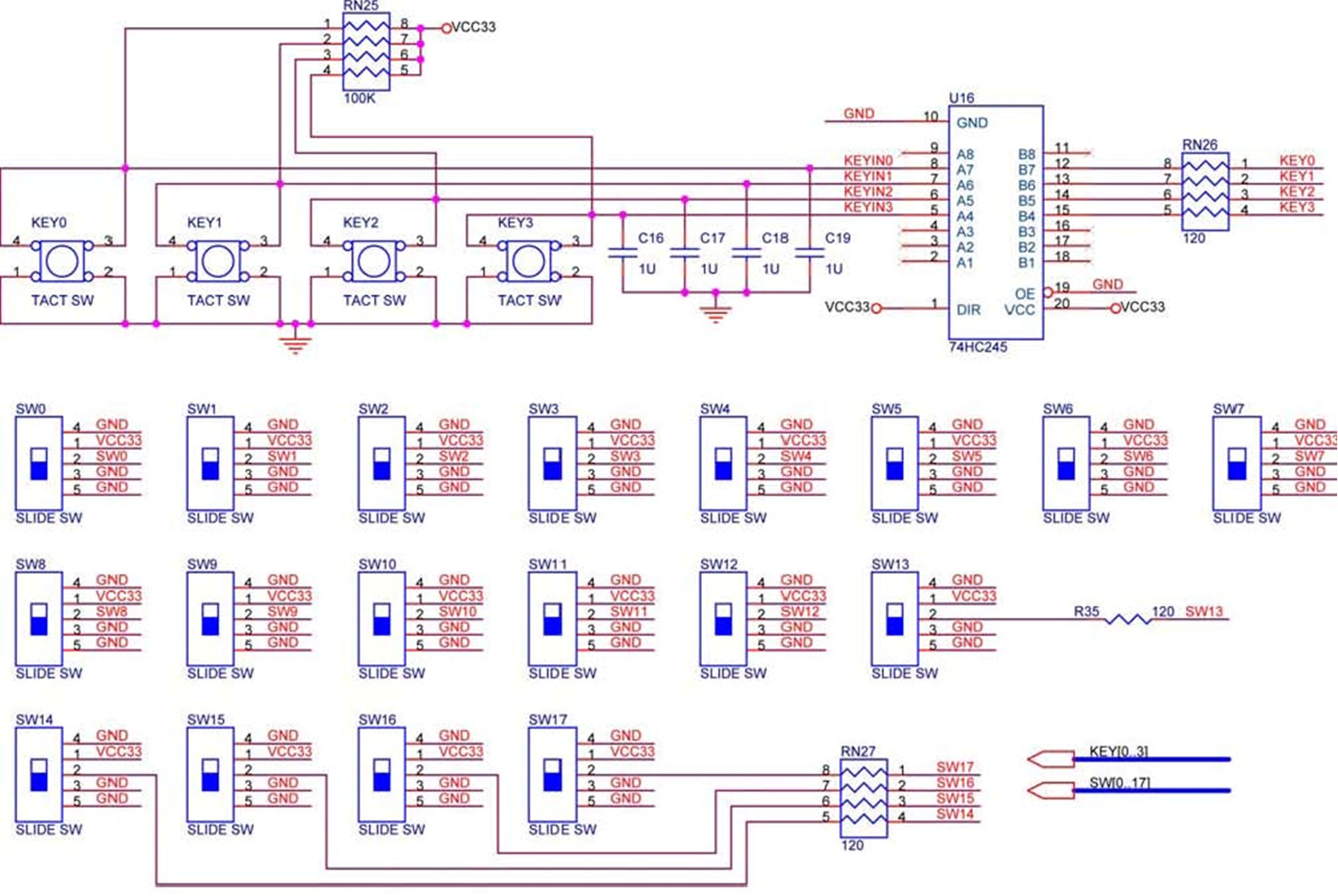
The DE2 board features four pushbutton switches, each of which is debounced using a Schmitt Trigger circuit, as shown in Figure 1. The outputs, labeled KEY0 to KEY3, from the Schmitt Trigger are directly connected to the Cyclone II...