
Remote-controlled fiber-optic Ceiling Light with Arduino

The circuit design employs an Arduino microcontroller to orchestrate the lighting effects of the LEDs. The use of four TIP122 transistors allows for efficient control of the high-brightness LEDs, ensuring that they can be driven adequately without exceeding their current ratings. Each transistor operates as a switch, enabling or disabling the flow of current to the respective LED based on the PWM signal received from the Arduino.
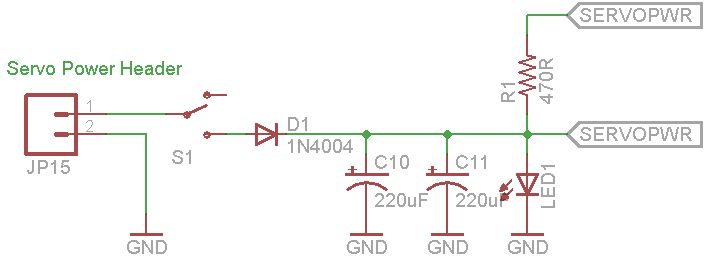
The configuration of the circuit includes a series connection of LEDs, which helps to maintain uniform brightness across the illuminators. The choice of a 470 Ω resistor in the power supply line is critical for current limiting, preventing excessive current from damaging the LEDs. The PWM control mechanism provides the ability to adjust the brightness of the LEDs dynamically, allowing for various lighting effects such as fading and color transitions.
The Arduino code provided includes functions for initializing the LEDs, receiving infrared signals, and controlling the fade effects of the LEDs. The use of a fade array allows for smooth transitions in brightness, enhancing the visual appeal of the lighting. The IR receiver component enables remote control of the lighting system, adding convenience and functionality to the design.
The overall schematic illustrates a well-organized and efficient control system for the LED illuminators, showcasing the integration of optical fibers with modern electronic components to achieve a sophisticated lighting solution. The design exemplifies the effective use of basic electronic principles combined with programming to create an interactive and visually engaging lighting system.A wood table with many holes with different diameters that house the optical fibers. The size of the ceiling lamp (90 cmx 60 cm) did not allow me to use a single bundle of fibers and this is the reason of the two beams I used, each of which comes with a LEDs illuminator as shown: The schematic with Arduino and its control circuit is shown in the figure above: it is a very simple circuit that I built on a breadboard. To control the high-brightness LEDs I used 4 transistors TIP122 whose base is driven with a PWM signal generated by Arduino. Each Arduino PWM output in connected to the each transistor base via a resistor of 1 kohm. The same type of LEDs are connected in series and hosted one in the first illuminator and the other in the second.
The line is connected to the positive external power supply via a 470 Ohm resistor. The transistor connected to the white LEDs is connected to pin 10 of Arduino, the TIP122 of the red LEDs to pin 9, the green LEDs to pin 6, that of the blue LEDs to pin 5. #include
enableIRIn(); // Start the receiver //Serial. begin(9600); } // Compare two tick values, returning 0 if newval is shorter, // 1 if newval is equal, and 2 if newval is longer // Use a tolerance of 20% int compare(unsigned int oldval, unsigned int newval) { if (newval < oldval *. 8) { return 0; } else if (oldval < newval *. 8) { return 2; } else { return 1; } } /* Converts the raw code values into a 32-bit hash code. * Hopefully this code is unique for each button. */ unsigned long decodeHash(decode_results *results) { unsigned long hash = FNV_BASIS_32; for (int i = 1; i+2 < results->rawlen; i+) { int value = compare(results->rawbuf[i], results->rawbuf[i+2]); // Add value into the hash hash = (hash * FNV_PRIME_32) value; } return hash; } void _initLeds() { for (int i=0; i<4; i+) { pinMode(pinLed[i], OUTPUT); analogWrite(pinLed[i], LOW); } } void _LedRGBOn() { for (int i=0; i<3; i+) { analogWrite(pinLed[i], 255); } } void ledFade(int ledpin, int time_wait) { for (int i=0; i<17; i+) { int j=16; analogWrite(ledpin, fade[j-i]); delay(time_wait); } delay(time_wait); for (int i=16; i>=0; i-) { int j=16; analogWrite(ledpin, fade[j-i]); delay(time_wait); } } void twoLedFade(int ledpin1, int ledpin2, int time_wait) { for (int i=0; i<17; i+) { int j=16; analogWrite(ledpin1, fade[j-i]); analogWrite(ledpin2, fade[i]); delay(time_wait); } delay(time_wait); for (int i=16; i>=0; i-) { int j=16; analogWrite(ledpin1, fade[j-i]); analogWrite(ledpin2, fade[i]); delay(time_wait); } } void threeLedFade(int ledpin1, int ledpin2, int ledpin3, int time_wait) { if ( _loop ) { for (int i=0; i<17; i+) { int j=16; analogWrite(ledpin1, fade[j-i]); analogWrite(ledpin2, 0); analogWrite(ledpin3, 0); delay(time_wait); } delay(time_wait); } for (int i=16; i>=0; i-) { int j=16; analogWrite(ledpin1, fade[j-i]
🔗 External reference
Related Circuits
This document explains how to utilize an Arduino to control up to 12 servos simultaneously with minimal jitter. A straightforward serial interface allows for the control of the position of these 12 servo channels. Additionally, it is possible to...
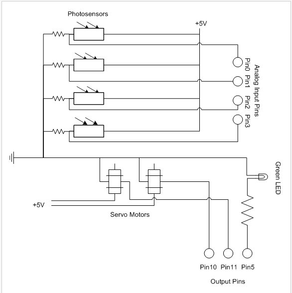
The PhytoBot is a semi-intelligent plant that reacts to external stimuli, specifically light intensity and light location, mimicking the behavior of a phototropic plant. It is designed as an interactive artwork intended for prolonged operation. The motivation behind this...
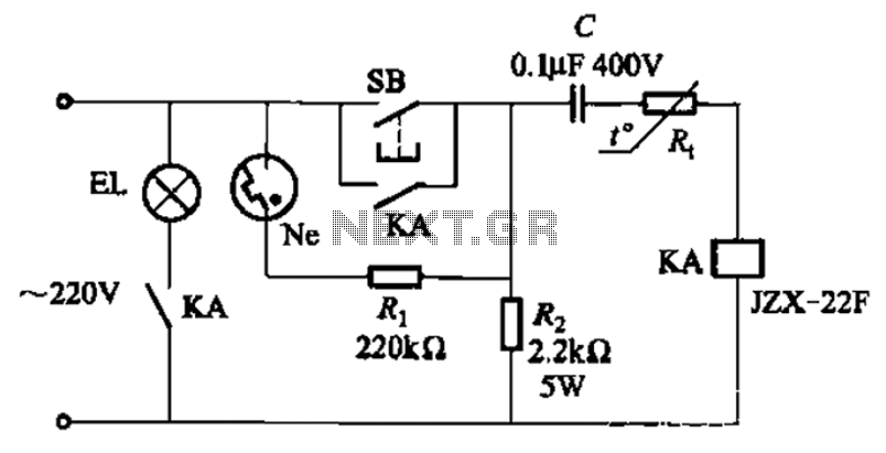
The circuit illustrated in Figure 2-49 is straightforward, featuring a cold Positive Temperature Coefficient (PTC) thermistor element. It utilizes the thermal resistance characteristics of the lamp to manage the delay time, which typically ranges from 10 to 30 seconds....
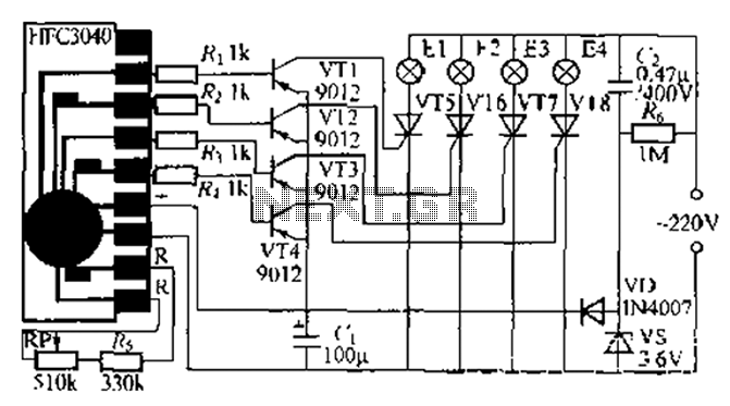
The circuit utilizes a four-way slowly dimming LED driver integrated with iU shoe production and a Qis four flashing lights string controller. The C3484 manifold is specifically designed to operate Ji lights with four lights that flash and slowly...
The light from a flashlight is directed at a phototube, which activates a CMOS logic circuit powered by a battery. This circuit controls the switching action to turn the motor of a model train or other electric toys on...
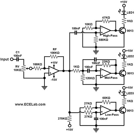
The simple circuit for converting an audio signal. The circuit basically consists of a buffer/amplifier stage and three filter circuits. The audio signal conversion circuit is designed to process audio signals efficiently while maintaining signal integrity. The circuit architecture includes...