
Remote Selection Video Switch

The A/B switch circuit is designed for flexible signal routing and can be effectively utilized in various electronic applications. The core of the circuit features the 4011 quad 2-input NAND gate, where two gates are configured to function as a monostable multivibrator. This configuration allows for a single pulse output when the switch SI is pressed, effectively creating a trigger signal. The monostable multivibrator output is fed into a 4017 decade counter, which counts pulses and is configured to recycle after reaching a count of two. This means that each time switch SI is pressed, the output of the 4017 changes state, allowing for toggling between two outputs.
The outputs from the 4017 IC, specifically pins 2 and 3, are utilized to control the 4066 quad bilateral switch (U3). The 4066 is capable of passing analog signals and can switch between different signal paths based on the control inputs from the 4017. When a control input is activated, it selects either output J1 or J2, enabling or disabling the corresponding signal path. This functionality is essential for applications where signal routing is required based on specific conditions or inputs.
For enhanced versatility, the circuit can be modified to allow for automatic triggering at a set rate. This could be achieved by integrating a timer circuit or additional components that generate periodic pulses, thus automating the switching process. Furthermore, by adding another 4066, the design can be expanded to accommodate multiple channels, potentially up to eight, which significantly increases its applicability in complex systems.
In practical applications, such as security surveillance systems, this A/B switch circuit can be employed to alternate between different video feeds or sensors, allowing for dynamic monitoring of various locations. The ability to control signal paths efficiently and automatically makes this circuit valuable in scenarios requiring real-time decision-making and signal management. The A/B Switch circuit consists of three ICs and a handful of resistors. Two gates from a 4011 quad 2-input N AND gate (U1A and U1B) are configured as a monostable multivibrator that, when switch SI is pressed, triggers a 4017 decade counter/divider, which has been set to recycle after a count of two. The outputs of U2 at pins 2 and 3 are fed to the control inputs of U3 (a 4066 quad bilateral switch) at pins 12 and 13.
Depending on which control input is high, either the J1 or J2 output is selected. With a little modification, the switch could be set to trigger at a set rate (automatically). With the addition of another 4066, it could have as many as 8 channels. One possible application would be in a security surveillance system.
Related Circuits
The receiver provides two TV signals, one for the living room and another for the bedroom, along with a satellite receiver. Watching television in the bedroom is convenient in Taiwan; however, when watching television in the living room, it...
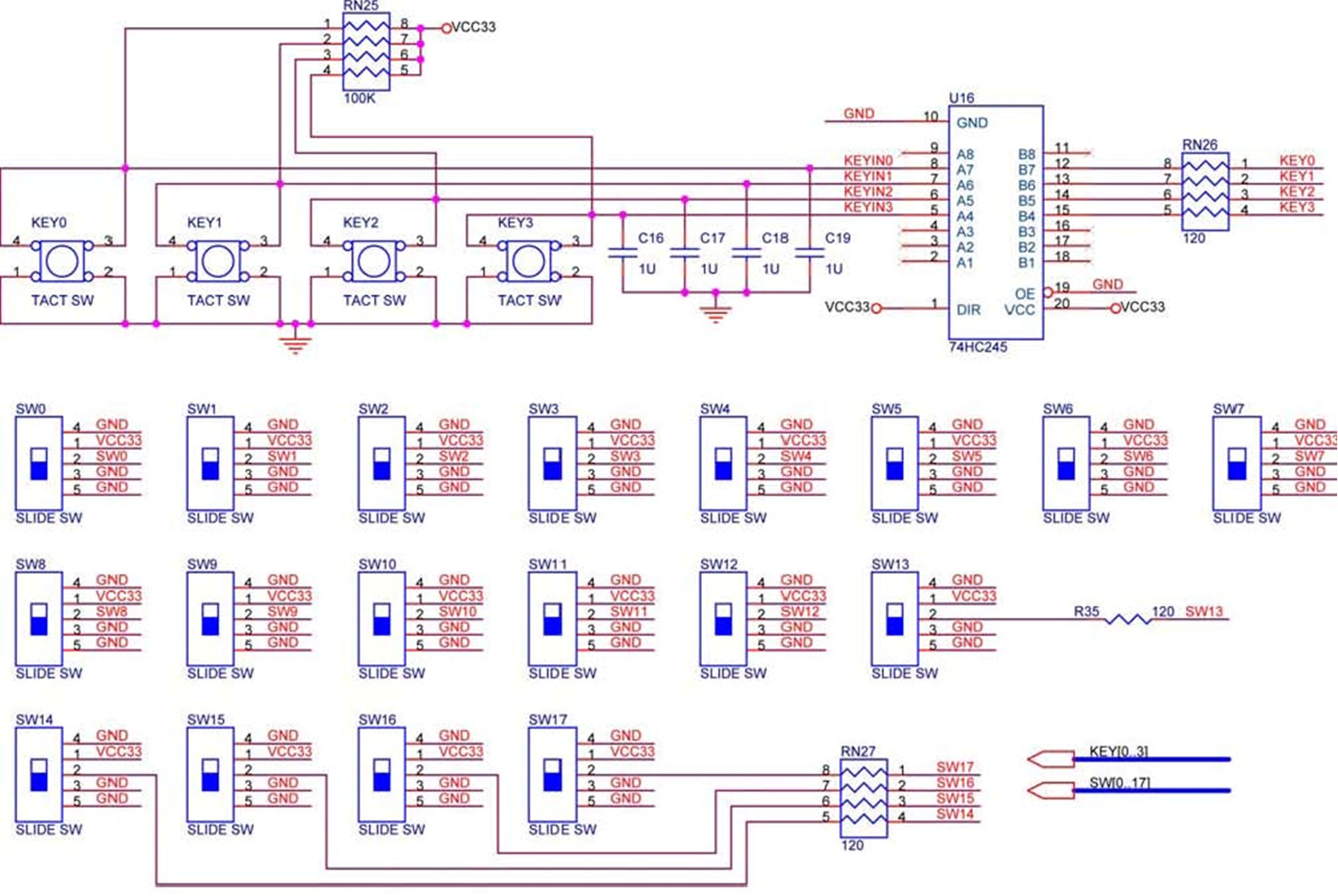
The DE2 board features four pushbutton switches, each of which is debounced using a Schmitt Trigger circuit, as shown in Figure 1. The outputs, labeled KEY0 to KEY3, from the Schmitt Trigger are directly connected to the Cyclone II...
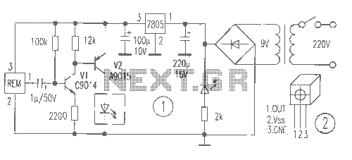
This is a remote tester circuit designed to test TV and other remote controls. The circuit is simple and utilizes only a few components. The infrared sensor used in the circuit is the TSOP1738. When the infrared waves are...

With a handful of inexpensive components, a little creativity, and the power of PicBasic, you can build some pretty outstanding robotics creations as Rob Arnold proves with his Ruf-Bot project. RF remote control is just way too cool not...
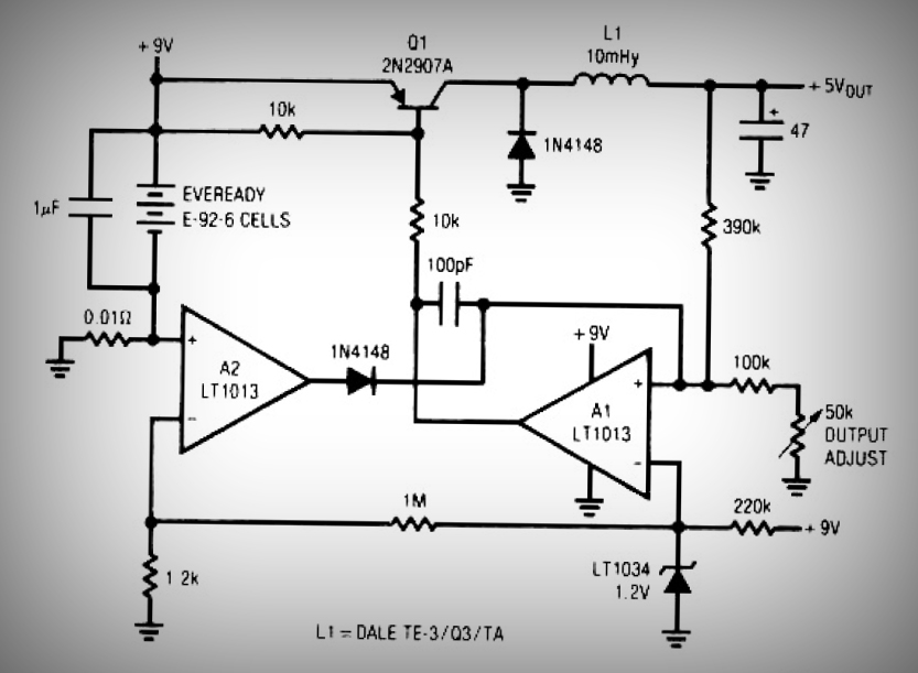
This circuit is a simple battery-powered switching regulator that provides a 5V output from a 9V source with 80% efficiency and a 50 mA output capability. When Q1 is on, its collector voltage increases, causing current to flow through...
It is necessary to adjust the 10K potentiometer while aiming the device at the television to obstruct the infrared rays from the remote control. This adjustment can be achieved through a process of trial and error. The circuit in question...