
Reverse engineering an MB Electronic Simon game

In the single-player mode, the game generates a sequence of lights and sounds that the player must follow. The sequence increases by one color each turn and ends when the player makes an error or reaches the maximum number of colors in the sequence, which varies based on the skill level setting. In multiplayer mode (game 2), the game starts with Simon displaying a color; the first player must repeat the color and then select another. Subsequent players must enter the current sequence and add one more color, continuing until a player makes an error or a sequence of 31 colors is reached. In multiplayer mode (game 3), the gameplay is similar to game one, but each player has one or more colors to press during the sequence. If a color is incorrectly selected, that color is removed from the game, and play continues until only one color remains (the winner). To play games 2 and 3, the skill level selector must be set to position 4, or the game will end prematurely, as the skill level setting affects all game modes; in multiplayer games, the maximum sequence number Simon can handle determines the length of gameplay.
The game hardware includes four colored lenses that operate switches on the circuit board when pressed. The colors, starting from the top left and moving clockwise, are red, blue, yellow, and green on the Pocket Simon, while the full-size version has green, red, blue, and yellow. There are two sliding switches on the game (the full-size version includes an additional on-off switch, which is replaced by a two-pole game switch in the pocket version). The internal hardware of Pocket Simon consists of a single-sided circuit board with four components and two integrated circuits, all soldered directly to the board. One component is a C2 47nF capacitor (an older style capacitor with the color code yellow, violet, brown, silver, silver) that can be replaced with an equivalent ceramic capacitor (often marked as 471).
By taking a top view of the circuit board and processing it in image editing software, a clearer view can be created to facilitate the conversion of the circuit into a schematic diagram. This involves filling the tracks on the PCB with black and the remaining items with white, with labels added for easier circuit tracing. By tracing the tracks on the circuit board and utilizing the available datasheet for the SN75494N chip, the schematic for the Pocket Simon circuit can be drawn. The only difference between the Pocket Simon and the full-size Simon is the addition of a diode across the speaker in the full-size version (typically used to prevent power surges from the speaker), which is unnecessary for the Pocket Simon that employs a buzzer instead, and the arrangement of the lights connected to the SN75494N chip. An analysis of the hardware can be conducted to further understand the circuit design and functionality.The MB Electronics Pocket Simon game has a very simple circuit thanks to the inclusion of a custom MB Electronics processor (the MB4850) which performs nearly all of the functions for the game. The only other significant piece of electronics is a SN75494N chip which interfaces the processor to the light bulbs and the built in piezo buzzer.
The a im of this exercise is to reverse engineer the Pocket Simon game so that it can be replicated as accurately as possible using modern components (or even reproduced entirely in software). This includes analysing the hardware (how it is built and how it works), the software (including timing, note frequencies, game modes, light sequences, etc.
). Since the processor of the Pocket Simon is the same as found in the full size Simon all information contained in this document are relevant to both (I chose the Pocket Simon since I didn`t want to risk damaging my full size game). Single Player The game generates a sequence of lights and sounds which the player must follow, the sequence grows by one colour every turn and ends when the player makes a mistake or repeats the maximum number of colours in a sequence (which is dependent on the skill level setting) Multi Player (game 2) The game begins with Simon displaying a colour, the first player must repeat the colour and then select another colour, subsequent players must enter the current sequence and then add one more, the next player then selects the sequence of colours entered so far and then one more and so on until a player makes a mistake (or a sequence of 31 colours is achieved).
Multi Player (game 3) This game is identical to game one, however each player owns one or more colours and is responsible for pressing it during the sequence. If a colour is incorrectly selected that colour is removed from the game and the game continues (with a new colour sequence) until only one colour is left (the winner) To play games 2 and 3 the skill level selector must be in position 4 or the game will end prematurely (this is due to the skill level` performing the same function in all game modes; in the multi player games the maximum sequence number Simon can handle gives the longest game play).
The game hardware consists of 4 coloured lens which, when pressed, operate switches on the circuit board. The colours from top left going clockwise are red, blue, yellow and green on the Pocket Simon and green, red, blue and yellow on the full size version.
There are 2 sliding switches on the game (on the full sized game there is an additional on off switch which in the pocket version is replaced by a two pole game switch): The internal hardware of Pocket Simon consists of a single sided circuit board containing 4 components and 2 integrated circuits (all soldered directly to the circuit board): C2 47nF capacitor (this is an old style capacitor with colour code yellow, violet, brown, silver, silver and can be replaced with an equivalent ceramic capacitor (usually marked 471`) By taking the top view of the circuit board and processing it in Photoshop it is possible to make a better view to allow the circuit to be converted back into a schematic diagram. To do this all the tracks on the PCB are filled with black and the remaining items filled with white.
The labels can be added to make tracing the circuit easier, resulting in the following picture: By tracing the tracks on the circuit board and using the available datasheet for the SN75494N chip it is possible to draw the schematic for the Pocket Simon circuit which is shown in the following diagram: The only difference between Pocket Simon and the full size Simon is the addition of a diode which sits across the speaker (usually a diode is used to prevent power surging from the speaker; since the Pocket Simon uses a buzzer instead it is not required) and the order of the lights connected to the SN75494N chip. In order to analyse the hardware a 🔗 External reference
Related Circuits
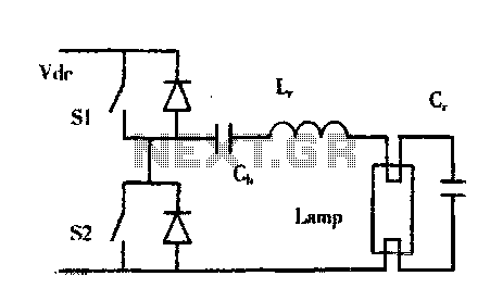
The construction of buildings, when full power is not required, utilizes dimmable electronic ballasts for continuous fluorescent operation, which can further reduce power consumption. Most modern designs and research on electronic ballasts recommend using resonant converter power circuits to...

This is a circuit design for a PWM speed control circuit for DC motor rotation. The circuit features two functions: Forward-Reverse operation and Regenerative Braking. The control is achieved using a MOSFET. The circuit allows for the control of...
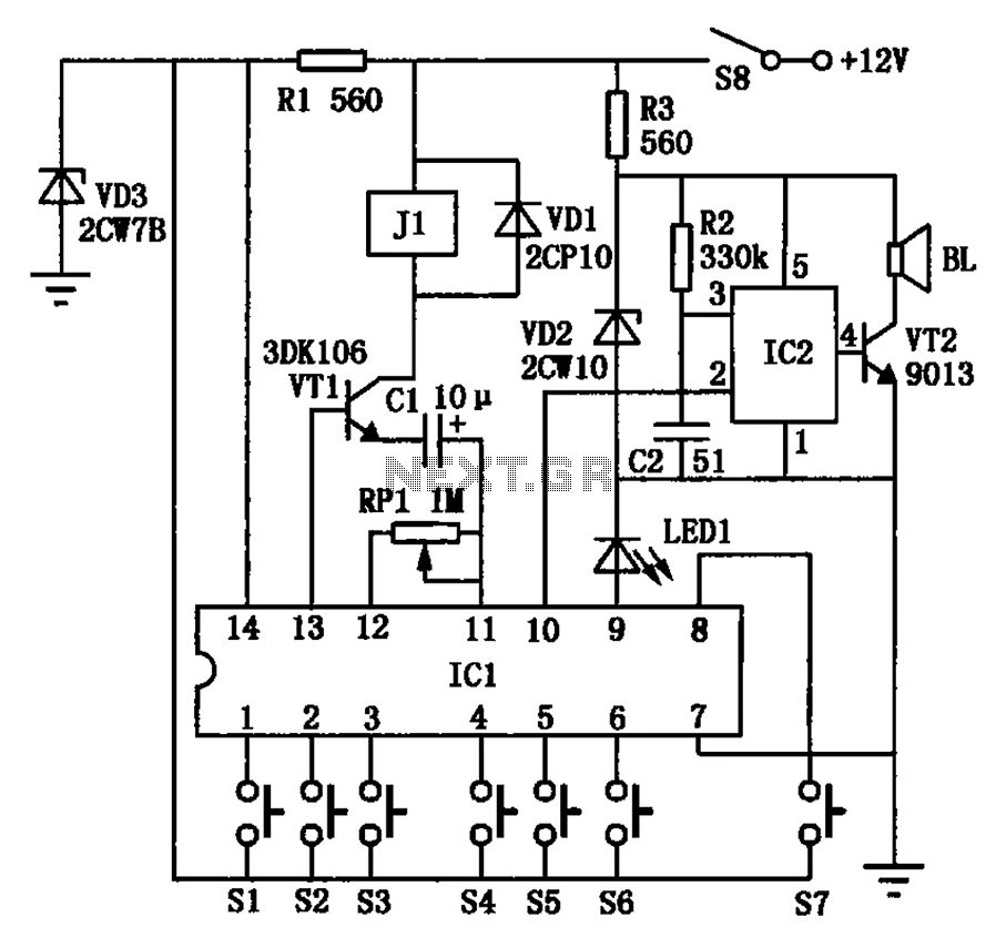
The automotive electronic locks circuit principle is illustrated with the dedicated lock IC 5G058. It features an external key switch connected to the positive power supply. The circuit includes six valid input keys, unlock keys S1 to S6, which...
The alarm will switch off when the 4 keys connected to "A,B,C,D" are pushed in the right order. The circuit works because each gate stands upon its predecessor. If any key other than the correct key is pushed, then...
The following circuit illustrates the Weller WLC100 Electronic Soldering Station Circuit Diagram. This circuit utilizes the Q4012LPH Transistor. Features include safety measures, temperature control, and functionality as a soldering station that performs effectively for various applications. It is a...
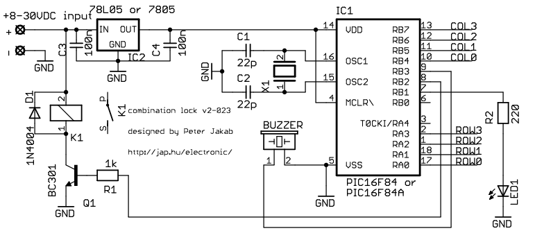
This is my electronic combination lock to use with an outdoor gate. The functionality is implemented in software. It turns on a relay (usually to open a door) for a few seconds if someone enters the valid code. This...