
AM radio circuit chip

The described AM radio circuit operates by utilizing a monolithic design that integrates multiple functions into a single chip, enhancing performance and reducing size. The antenna captures the AM broadcast signals, which are then directed to a high-efficiency mixer. This mixer plays a crucial role in converting the incoming radio frequency signals to a lower intermediate frequency, which is easier to process.
The output from the mixer is fed into an IF transformer, which serves to filter out unwanted frequencies and isolate the desired signal. This filtering process is vital for ensuring that only the relevant audio information is passed on to the next stage of the circuit. After filtering, the signal is directed to IC1, where it is further processed.
In IC1, the signal undergoes amplification through a detector circuit. This amplification is necessary to boost the audio signal to a level suitable for output. The output is provided at a 13-pin configuration, which allows for connection to additional audio processing components or directly to a speaker system, enabling the listener to hear the broadcasted audio clearly.
This circuit design is efficient and compact, making it suitable for various applications, including portable radios and integrated audio systems. The use of a monolithic approach not only simplifies the design but also enhances reliability and reduces manufacturing costs.AM radio shows monolithic circuit. The broadcast signal received by the antenna foot iciCD fed by a high efficiency mixer, the output from IF, IF transformer after filtering, a nd then into the feet IC1, after amplification by the detector in ICI, 13-pin output audio signal .
Related Circuits
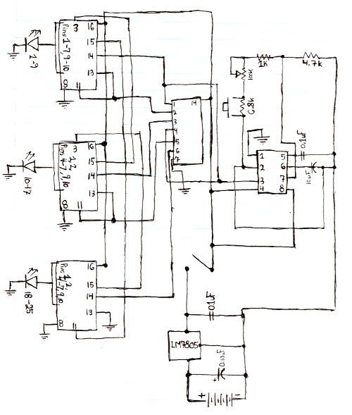
Here is the schematic for the circuit. Solder all the components onto a perfboard. The drawings may not be very clear. Essentially, the 555 timer generates a pulse. The circuit utilizes a 555 timer IC configured in astable mode, which...

This circuit was utilized with an audio power amplifier to identify the point at which the output is -3 dB from maximum, indicated by LED D5, and at clipping, shown by LED D6. The indicator can be employed with...
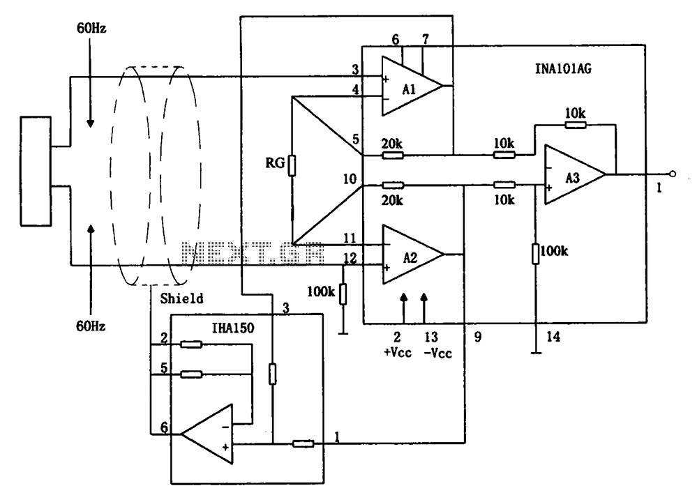
The circuit diagram illustrates a hum elimination instrument amplifier circuit. The amplifier stages A1 and A2 utilize the integrated operational amplifier INA101, followed by stage A3 which employs the INA105. A feedback circuit is incorporated to reduce the power...
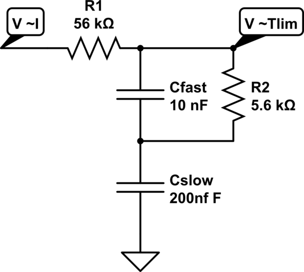
A MOSFET is employed to drive a load that includes a sense resistor in its current path. The voltage across this resistor is utilized to trigger a circuit capable of disconnecting the load in the event of an overcurrent...
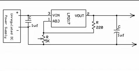
One aspect that was overlooked regarding the battery circuit is the attempt to salvage the circuit and integrate it with the new battery. The battery circuit in question likely involves several key components that are essential for proper functionality. Typically,...
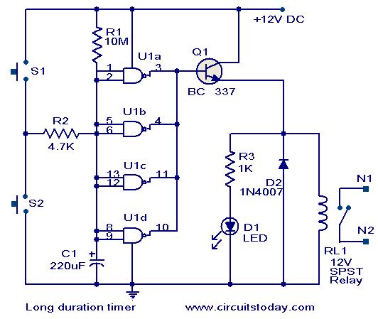
This timer circuit is designed to turn off a specific device after approximately 35 minutes. It can be utilized to switch off appliances such as radios, TVs, fans, and pumps after a predetermined duration of 35 minutes, contributing to...