
1 500-W Rf Amplifier
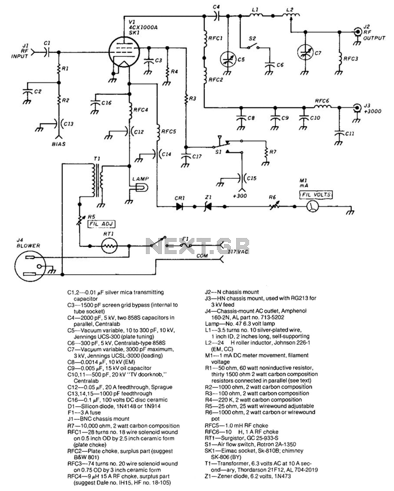
This amplifier design operates within a frequency range of 1.8 to 54 MHz, making it suitable for various RF applications. The RF drive requirement of approximately 30 W indicates that this amplifier is capable of delivering significant power output, which is essential for effective signal transmission.
The design emphasizes the importance of shielding the grid compartment from other circuit elements, particularly the output circuitry, to minimize interference and maintain signal integrity. The use of high-quality capacitors is evident, with components such as silver mica and vacuum variable capacitors chosen for their stability and performance under high voltage conditions. The capacitors used in this circuit have voltage ratings up to 10 kV, making them suitable for high-power RF applications.
The inclusion of multiple RF chokes and inductors indicates a focus on filtering and stabilizing the RF signal. The design utilizes solenoid-wound inductors to achieve the necessary inductance values while ensuring efficient performance. Resistors are carefully selected for their power ratings and types, including non-inductive and adjustable components, to allow for precise tuning and stability in the amplifier's operation.
The power supply and circuit protection features are also well-considered, with the use of a fuse and a Zener diode to safeguard against overcurrent and voltage spikes. The air flow switch suggests that thermal management is a priority, ensuring that the amplifier operates within safe temperature limits.
Overall, this amplifier schematic represents a robust design tailored for high-frequency applications, showcasing careful selection of components and thoughtful engineering to achieve reliable performance. The frequency range of this amplifier is 1.8 to 54 MHz. The amount of RF drive required for full output is about 30 W. The grid compartment (Rl, R2, RFC4, RFC5) should be shielded from the other circuitry—especially the output circuitry. C1,2—0.01 silver mica transmitting capacitor C3—1500 pF screen grid bypass (internal to tube socket) ca—2000 pF, 5 kV, two 858S capacitors in parallel, Centralab C5—Vacuum variable, 10 to 300 pF, 10 kV, Jennings UCS-300 (plate tuning) C6—-300 pF.
5 kV, Centra lab-type 858S C7—Vacuum variable, 3000 pF maximum, 3 kV, Jennings UCSL-3000 (loading) C8—0.0014 ftF, 10 kV (EM) C9—0.005 ftF, 15 kV oil capacitor C10,11 —500 pF. 20 kV ""TV doorknob," Centralab C12—0.05 pF, 20 Afeedthrough, Sprague C13,14,15—1000 pF feedthrough C16—0.1 /iF, 100 volts DC disc ceramic D1—Silicon diode, 1N4148 or 1N914 F1—3 A fuse J1—BNC chassis mount J2— chassis mount J3—HN chassis mount, used with RG213 for 3 kV feed J4—Chassis-mount AC outlet, Amphenol 160-2, AL part no.
713-5202 Lamp—No. 47 6.3 volt lamp L1 —3.5 turns no. 10 silver-plated wire, 1 inch ID, 2 inches long, self-supporting L2—24 roller inductor, Johnson 226-1 (EM, CC) M1—1 mA DC meter movement, filament voltage R1 —50 ohm, 60 watt noninductive resistor, thirty 1500 ohm 2 watt carbon composition resistors connected in parallel (see text) R2—1000 ohm, 2 watt carbon composition R3—100 ohm, 2 watt carbon composition R4—220 K, 2 watt carbon composition R5—25 ohm, 25 watt wirewound adjustable R6—1000 ohm, 2 watt carbon or wirewound pot R7—10,000 ohm, 2 watt carbon composition RFC1 —28 turns no. 18 wire solenoid wound on 0.5 inch OD by 2.5 inch ceramic form (plate choke) RFC2—Plate choke, surplus part (suggest B&W801) RFC3—74 turns no.
20 wire solenoid wound on 0.75 OD by 3 inch ceramic form RFC4—9 15 A RF choke, surplus part (suggest Dale no. IH15, HF no. 18-105) RFC5—1.0 mH RF choke RFC6—10 H, 1 A RF choke RT1—Surgistor, GC 25-933-S S1 —Air flow switch, Rotron 2A-1350 SK1 —Eimac socket, Sk-810B; chimney SK-806 (BY) T1 —Transformer, 6.3 volts AC at 10 A second— ary, Thordarson 21F12, AL 704-2019 Z1 —Zener diode, 6.2 volts, 1N473
🔗 External reference
Related Circuits
300W Subwoofer Power Amplifier. High power amplifiers are not common as projects, as they are inherently challenging to build and often expensive. A minor error during assembly can lead to significant issues. The 300W subwoofer power amplifier is designed to...
A Class A Class AB amplifier rated 100 Watts when driving a 4 ohm loudspeaker. This circuit developed out of my 30+ years of JLH class-A based investigations. The original simple 1969 JLH class-A design provided excellent first cycle accuracy...
This general-purpose amplifier has a bandwidth of approximately 20 MHz and it uses an LM733/NE592 video amplifier integrated circuit. This circuit can be utilized as a line driver or as a LAN line driver. The circuit employs the LM733/NE592 video...
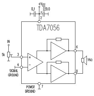
This TDA7056 power audio amplifier circuit diagram project is designed to deliver a maximum output power of 1 watt into an 8-ohm load when powered by a 6-volt supply, or a maximum output power of 3 watts into a...
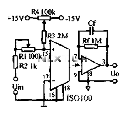
An adjustable gain test is conducted in preparation for an isolation amplifier circuit, utilizing the optical coupling isolation amplifier ISO100. This adjustable gain can form part of a test device for the isolation amplifier. The circuit gain can be...
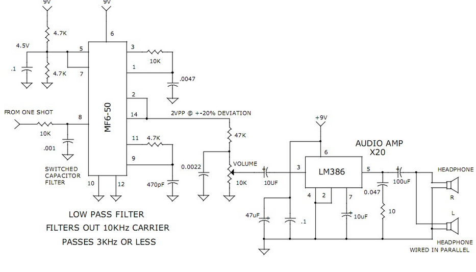
This circuit utilizes a switched capacitor filter integrated circuit (IC) from National Semiconductor to filter signals with frequencies exceeding 3 kHz, which are not required for voice audio. The circuit design incorporates a switched capacitor filter IC, which is a...