
Long-range high-frequency transistor FM transmitter circuit diagram

The circuit design employs the 3DA87C triode configured as a three-point oscillator, which is essential for generating the FM signal. The oscillator's operation relies on precise component values to ensure the output frequency falls within the FM band. The transistor's gain is a critical parameter, as it amplifies the oscillation signal, thus enhancing the transmitter's range. The choice of high-frequency ceramic capacitors is paramount to minimize losses at the operating frequencies and ensure stability in the circuit.
The inductor's configuration, with its specific number of turns and dimensions, plays a significant role in determining the resonant frequency of the oscillator. The center tap facilitates the connection to the antenna, which should be matched in length to optimize the radiation pattern and transmission efficiency. The use of a high-frequency transistor such as the C3355 significantly improves the circuit's performance, allowing it to operate effectively within the desired frequency range.
Finally, the circuit must be tested and tuned meticulously to achieve the best performance. This includes adjusting the variable capacitor and ensuring all connections are secure to minimize signal loss. The assembly should be housed in a suitable enclosure to protect the components and reduce interference from external sources. Following these guidelines will yield a reliable long-range FM transmitter capable of operating effectively within the FM spectrum.As shown in FIG ordinary triode 3DA87C to make long-range FM transmitter circuit, which is normal three-point oscillator circuit, the remote transmitter circuit with large current emissions, in open areas up to 1KM, according to the schematic assembly tests, the transistor magnification to choose flag with a blue dot is greater than 80 times, but found it not fall within 88-108MHZ normal frequency of the FM band, but no matter how to adjust the capacitance and inductance in the experiment, were lower than the 88MHZ about 25 percent more than a dozen MHZ frequency point, radio with TV audio reception function TESUN radio to function properly received, fT cutoff frequency parameter value of the transistor is not enough, not to mention its oscillation frequency to go up. In order to increase the distance between transmitter and receiver can change its frequency falls within the range of normal FM radio, had to look for another high-frequency transistor with D40, C1971, C1972, or as a high frequency oscillation power amplifier circuit, with its high-power output to increase the transmission distance, but such high-frequency transistor market is difficult to buy, and even buy, most of these fakes can not be used.
Later found with the C3355, this transistor cutoff frequency of several thousand MHZ, its power of 600MW, is sufficient for the FM band, then the circuit will make some improvements, can easily produce a long-range FM transmitter circuit. Select components: capacitors C2, C3, C4 are high frequency ceramic capacitors, Ct is 5 / 25P high-frequency semi-adjustable capacitor to be replaced with high-frequency ceramic value after completion of debugging test with a digital multimeter capacitance, L is a diameter of about 6 turns bodiless 8mm 0.9 enameled wire on the pipe, then opened about 2CM, center tap, using a TV antenna or a transmitting antenna in place with the same length of wire.
Actual debugging to the best of its transmission power maximum distance of not less than 500 meters.
Related Circuits
This is a highly stable, harmonic-free, long-range FM transmitter circuit designed for FM frequencies between 88 and 108 MHz. It is capable of covering a range of up to 5 km. The FM transmitter circuit operates within the designated frequency...
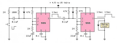
The LM555 timer circuit is similar to the previous design but incorporates two stages, allowing for control over both the pulse width and the delay. The LM555 timer is a versatile integrated circuit widely used in various timer, delay, pulse...

The electric sewing machine saving circuit is designed with a Hall switch integrated circuit (IC) and a relay (K). When the switch is closed, power is activated. The circuit includes a resistor (R) and a capacitor (Ci) for RC...
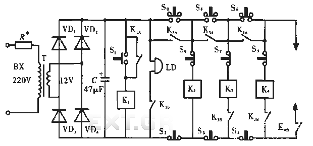
The circuit operates as illustrated in Figure 5-2a. It includes an alarm switch (S). When switch S is pressed, relay K is activated, which closes two normally open contacts. This action triggers the alarm bells. The alarm continues to...
This is a single transistor pump circuit. It is a straightforward circuit that is quite useful and can serve as a foundational component for designing more complex electronic systems. The single transistor pump circuit utilizes a transistor as the primary...
This circuit can detect whether a train is in a particular drive. The output is TTL and CMOS compatible and can be processed by such a computer. The simple circuit works. The driving voltage is connected to the two...