
27MHz CW transmitter
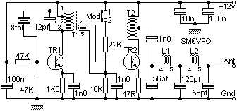
The power amplifier is quite straightforward. The amplifier is biased as a linear amplifier with the collector load matching the 200 Ohms collector impedance to 50 Ohms with T2. L1 and L2 plus the three capacitors for an output low-pass filter. Position the components on the board and solder them. The circuit is quite forgiving in that it can be built birds-nest/ugly-bug style and still have a clean output. Mine had all unwanted harmonics better than -45dBc.
The transistors can be 2N2222 or BC547 up to about 20MHz. After that the power starts to fall. Changing TR2 to BC108 is great to about 35MHz. Above 35MHz then BSX19 or BSX20 (a good RF transistor) should be used as the PA stage.
Modulation is applied to the base of TR2. The MOD link is removed and pin 2 is varied from 0vDC to 12vDC to vary the TX output power from zero to full power. Pins 1 and 2 may therefore be coupled directly to a Morse key and you have an HF bands QRP CW transmitter. The capacitor across the 10K resistor will also adjust the keying envelope. Leave it at 1n0 for radio control use, but increase it to 100nF for good Morse. On the band, this transmitter sounds surprisingly clean and well-formed. Since the oscillator is continuously running, there is absolutely no chirp. Adjusting the tuning of T1 will adjust the frequency by a couple of KHz.
The circuit design utilizes a compact PCB layout measuring 60mm x 35mm, which facilitates integration into various equipment enclosures. The design emphasizes modularity, allowing the transmitter to be tailored for different frequencies by simply swapping out the crystal and adjusting the coils. The oscillator stage is pivotal, with the ability to operate across a frequency range from 1MHz to 40MHz, depending on the selected crystal. The inherent flexibility of the design allows for operation at multiple harmonics, although output power diminishes at higher frequencies.
The power amplifier section is engineered for efficiency, employing a linear biasing configuration to ensure minimal distortion. The output stage utilizes a low-pass filter composed of inductors L1 and L2, along with capacitors, to attenuate unwanted harmonics and provide a clean output signal. The choice of transistors, such as the 2N2222 or BC547, is critical, with specific models recommended for optimal performance at varying frequency ranges.
Modulation is achieved through a straightforward approach, allowing for both amplitude modulation and continuous wave operation. The modulation input is designed for compatibility with a Morse key, enabling QRP operation on HF bands. The adjustable capacitor across the 10K resistor is a key feature, permitting fine-tuning of the keying envelope to suit different transmission needs.
Overall, this transmitter circuit is characterized by its simplicity, compactness, and adaptability, making it suitable for a range of amateur radio applications. The design ensures high-quality signal transmission while maintaining ease of assembly and flexibility in operation. The original TX was designed to be only PULSE Modulated for a proportional R/C system, but I later used the same circuit to make an HF bands Amplitude Modulation (AM) transmitter using PA-Base Modulation. It eliminated the need for a modulation transformer; it can be driven with a simple Op-Amp amplifier.
Frequency range of the original prototypes were as low as 1MHz and the top frequency was 40MHz. The circuit is the same, just the crystal and coils are changed. The CW output power is about 200mW at 29MHz. It is only 70mW Amplitude modulated, but modulation peaks can rise to 200mW with 80% modulation. The transmitter is quite small, only about 60mm. x 35mm. so it easily forms a single transmitter module inside the case of any other peice of equipment, such as an R/C transmitter or a Hamradio portable rig. This is the PCB version. The final PCB has had a couple of changes around the oscillator stage. The above table does NOT contain rules. You may have a 3.5MHz CW crystal, but there is no reason why you cannot tune the oscillator to 7MHz. It will work with the fundamental, 2nd harmonic, 3rd and 5th. The output power will reduce at higher harmonics and frequencies are chosen. The power amplifier is quite straight-forward. The amplifier is biased as a linear amplifier with the collector load matching the 200 Ohms collector impedance to 50 Ohms with T2.
L1 and L2 plus the three capacitors for an output low-pass filter. Position the components on the board and solder them. I don't think I can add more to that, except to say that you should follow the PCB board component layout I have given. Vertically mounted resistors have a long wire and a short wire. The long one should not have any RF on it. The circuit is quite forgiving in that it can be built birds-nest/ugly-bug style and still have a clean output.
Mine had all unwanted harmonics better than -45dBc. The transistors can be 2N2222 or BC547 up to about 20MHz. After that the power starts to fall. Changing TR2 to BC108 is great to about 35MHz. Above 35MHz then BSX19 or BSX20 (a good RF transistor) should be used as the PA stage. Modulation is applied to the base of TR2. The MOD link is removed and pin 2 is varied from 0vDC to 12vDC to vary the TX output power from zero to full power. Pins 1 and 2 may therefore be coupled directly to a morse key and you have an HF bands QRP CW transmitter.
The capacitor across the 10K resistor will also adjust the keying envelope. Leave it at 1n0 for radio control use, but increase it to 100nF for good morse. On the band this transmitter sounds surprisingly clean and well formed. Since the oscillator is continuously running, there is absolutely no chirp. Adjusting the tuning of T1 will adjust the frequency by a couple of KHz. 🔗 External reference
Related Circuits
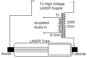
This set of two circuits forms the basis for a simple light wave transmitter. A laser beam is modulated and directed toward a receiver that demodulates the signal, subsequently presenting the information (voice, data, etc.). The assembly is straightforward and...
A 40kHz ultrasonic transmitter circuit consists of three oscillators (F1, F2, and F3), with F3 generating a 40kHz square wave output. The frequency is primarily determined by components C1, R1, and an adjustable resistor (RP). The excitation output from...
This circuit generates an FM modulated signal with an output power of approximately 500 mW. The microphone preamplifier is constructed using two 2N3904 transistors, with audio gain controlled by a 5 kΩ preset resistor. The oscillator is a Colpitts...
To replace a microphone with a 3.5" audio jack in a circuit, modifications will be necessary. The circuit currently utilizes an electret microphone, and adjustments must be made to accommodate the audio jack for audio transmission. The audio jack...
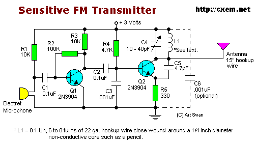
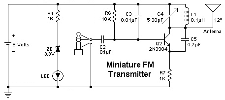
Sensitive FM Transmitter. Additional Notes: The default for the capacitors type is ceramic, preferably the NPO 1% type or equivalent. However, nothing critical is here; any type can be used. The sensitive FM transmitter circuit is designed to operate in...
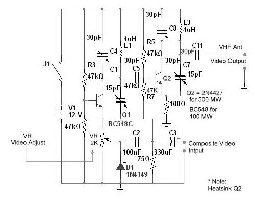
Tuned circuits consist of C4, L1, C8, L3, and two 15 pF trimmer capacitors positioned across the collectors and emitters of both transistors. Other NPN transistors such as BC54, 2N3642, and 2N3643 may also be suitable. The circuit is...