
RGB LED experiment Arduino
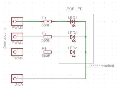
An RGB LED driver circuit utilizes a microcontroller, such as an AVR or Arduino, to control the brightness of red, green, and blue LEDs through PWM (Pulse Width Modulation) signals. The circuit typically consists of the RGB LED connected in series with current-limiting resistors to protect the LEDs and the microcontroller. The resistors are calculated based on the forward voltage of the LEDs and the desired current, typically around 20mA for standard brightness.
The microcontroller's PWM outputs are configured to control each color channel independently, allowing for the mixing of colors by adjusting the duty cycle of each PWM signal. The duty cycle determines the proportion of time the LED is turned on versus off, effectively controlling the perceived brightness.
For color mixing, the user can program the microcontroller to generate various color combinations by varying the PWM signals. This can be enhanced by implementing algorithms for HSL-to-RGB conversion, enabling a more intuitive way to select colors based on hue, saturation, and lightness. The conversion process involves calculating the RGB values from the desired HSL values, which requires understanding the relationships between the color components.
In terms of physical setup, it is advisable to use a breadboard for prototyping, allowing for easy adjustments and modifications. The suggestion to use a paper tube for light diffusion is practical, as it helps to create a more uniform light output and can enhance the visual effect of the color mixing.
Overall, this RGB LED driver project serves as an excellent educational tool, demonstrating fundamental concepts in electronics, programming, and color theory while providing a platform for experimentation and creativity.This evening as I came home from a paragliding appointment, I had a feeling that I must improve my yesterday-written RGB LED driver code. So I cleaned it up a bit, and wrote a lot of comments to make it more useful for educational purposes.
I`m alredy over this level, but it`s fun to play with it. An RGB LED is just three LEDs in a single package: red, green and blue, from here comes the TLA. If you have no RGB LEDs currently, you can replace it with a red, a green and a blue LED. For a good result, the LEDs` (visible) brightnesses have to be similar. The idea is, that from the three basic colors (r, g, b) a lot of colors (but not all) can be mixed. This mixing is performed by three individual PWM signal applied by the AVR controller on the Arduino board.
See more about PWM at. I think the whole thing is very simple, but it looks nice, and you can experiment with the generation of different waveforms. Try to modify the code to use a harmonic (sine) function as input for the lightness. For more advanced users: avoid the built-in sin() function, but produce sinusoidal output. Hint: arrays This video may not be as exciting as the previous one (see here ) because my phone`s camera is unable to capture the fine changes in the color of the LED.
It seems much more better in reality, so you really must build one. The other side of the breadboard (and the rest of the parts)is used in another project and it`s not connected to the board now. I was just too lazy to disassemble it. This doesn`t need explanation. Just connect your RGB LED to the Arduino board in series with three 560 © resistors as you can see on the figure above.
(200 © is fine too these resistors define the current which flows through the LEDs. The current cannot exceed 50mA (each), as it could damage the microcontroller and the LED too. ) If you have individual LEDs for red, green and blue, it`s fine too. Tip: put the RGB LED or the three individual LEDs in a thin paper tube as it can be seen on my video. It diffuses and mixes the light and it becomes less direct. Well, the pass-by-reference can be a bit difficult to understand, but when every byte of the memory worth a lot because of the limited space, which can happen often especially in microcontroller systems it`s very important.
And it speeds things up too. Read more at The interesting part is the HSL-to-RGB conversion. HSL means hue-saturation-lightness and it`s a more natural description of colors than the RGB. However, RGB must be applied to the outputs since we only have red, green and blue LEDs. And that`s why you need to convert. 🔗 External reference
Related Circuits
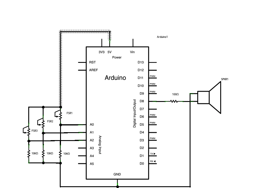
Power three force-sensitive resistors (FSRs) or any other analog sensor with 5V in parallel. Connect each sensor to analog pins 0-2, utilizing a 10K resistor as a reference to ground on each input line. The provided sketch reads three...
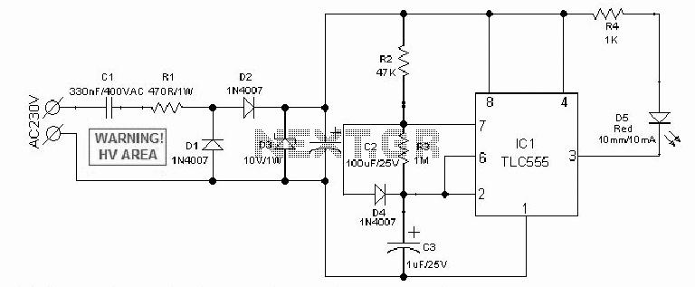
An AC mains operated single LED flasher circuit is designed using the widely used CMOS timer chip TLC555. The entire circuit is powered directly by the grid supply of 230VAC through a capacitive potential divider and associated components. This LED...
Several 1.5 V LED flasher circuits can be found online, and four of them are presented here. The flasher circuits operate on a single 1.5 V power supply. The design of a 1.5 V LED flasher circuit typically involves a...
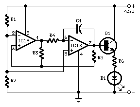
This circuit operates a LED in pulsing mode, i.e. the LED goes from off state, lights up gradually, then dims gradually, etc. This operation mode is obtained by a triangular wave generator formed by two op-amps contained in a...
Many educational haptic feedback devices utilize kinesthetic force feedback systems like the Novint Falcon and the Phantom Omni. While these devices are relatively affordable compared to higher-end haptic systems, they remain costly for educational purposes. Consequently, a team has...
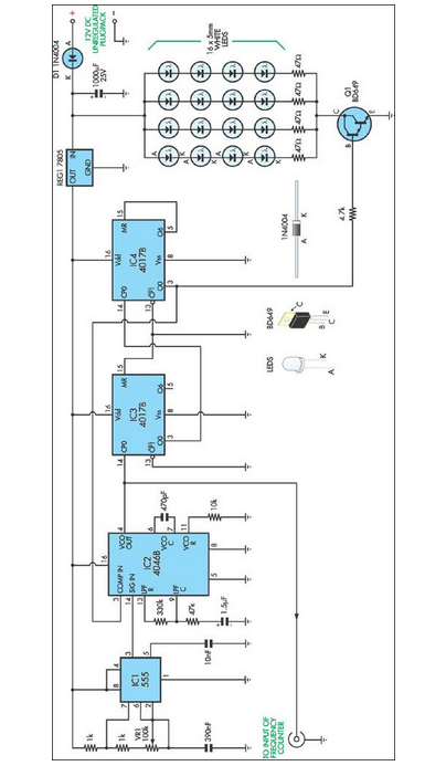
This stroboscope circuit utilizes 16 high-brightness white LEDs housed within a torch structure. It also offers a signal output to a frequency counter to indicate revolutions per minute (RPM). The stroboscope circuit is designed to provide visual indication of rotating...