
Rgb/Ntsc Converter

The circuit employs the Motorola MC1377 integrated circuit, which is designed specifically for video signal processing. It converts RGB signals, typically used in computer graphics and high-quality displays, into the NTSC format suitable for standard television broadcasts. The MC1377 achieves this by taking the three separate color signals (Red, Green, and Blue) and combining them into a composite video signal.
Resistor R7 plays a crucial role in setting the gain of the circuit. Its 1% tolerance ensures that the gain remains consistent, which is important for maintaining video quality and preventing distortion. A variation in this resistor's value could lead to significant differences in output brightness and color accuracy.
Capacitor CB, with a tolerance of 2%, is likely involved in filtering or coupling within the circuit. The tolerance level is important as it affects the frequency response and stability of the video signal. A capacitor with too high a tolerance could introduce unwanted noise or signal degradation, impacting the overall performance of the video output.
In summary, this circuit design effectively transforms RGB signals into an NTSC video format, ensuring high fidelity in color reproduction and signal integrity through careful selection of component tolerances. Using a Motorola MC1377, this circuit produces NTSC video from an RGB source. Components are not critical, except for R7 and CB, which should be 1% and 2% tolerance, respectively.
Related Circuits
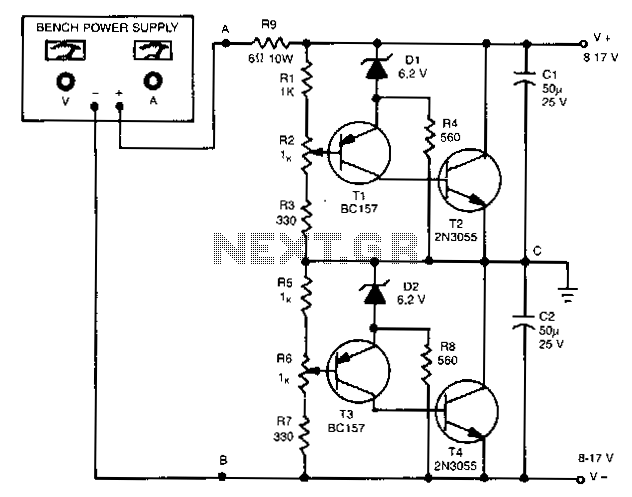
The outputs in this circuit are independently variable and can be loaded unsymmetrically. The output voltage remains constant, regardless of load and changes. By varying potentiometers R2 or R6, the output voltages can be conveniently set. Outputs can be...
VD represents the voltage drop across the diode, while VTrans indicates the voltage drop across the transistor. The boundary between continuous and discontinuous operation occurs when the output current (io) is zero. A primary consideration in converter design is...

The circuit is designed to convert sinusoidal input signals into TTL output signals and can process input voltages exceeding 100 mV. This circuit typically employs a comparator to achieve the conversion from sinusoidal to TTL levels. The sinusoidal input signal...
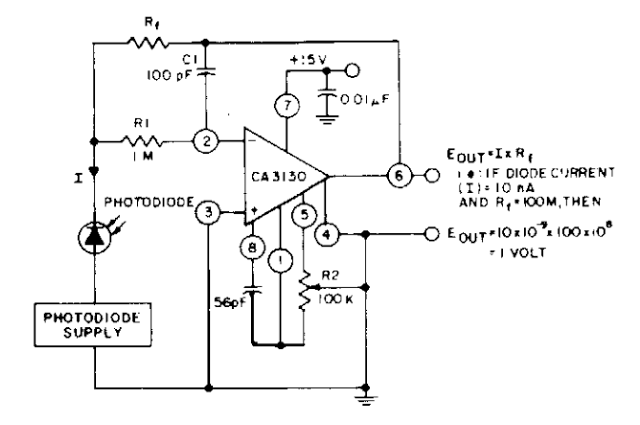
The photodiode current-to-voltage converter circuit employs three CA3130 BiMOS operational amplifiers, designed for applications that require sensitivity to sub-picoampere input currents. This circuit generates a ground-referenced output voltage that is directly proportional to the input current flowing through the...
The limitation of car supply voltage (12V) forces to convert the voltages to higher in order to power audio amplifiers. This supply is intended for two channels with 50W max each (of course it depends on the amplifier used)....
A tachometer can be constructed using the TC9400 in frequency-to-voltage (F/V) mode to convert frequency information (RPM) into a linearly proportional voltage. This voltage can then be compared to one of several comparators (in this example, using eight). The...