
Ring Generator Using a Transformer

The described ring generator circuit is designed to produce an audible ringing signal for a telephone at regular intervals. The key components include a transformer, a resistor, capacitors, and specific semiconductor devices (IFR510 and 556).
The circuit utilizes a small 12.6 VAC power transformer, which provides the necessary AC voltage to generate the ringing signal. The 120 volt side of the transformer is stepped down to the required 12.6 volts, which is then rectified and processed to produce a 70 volt AC ringing voltage at a frequency of 30 Hz. This ringing voltage is essential for signaling the telephone.
The interval between the rings is adjustable, allowing for customization based on user preference. This is achieved through the use of a 1 Megohm resistor, which can be replaced with a variable resistor (potentiometer) for further flexibility in timing adjustments. By changing the resistance value, the time delay between rings can be increased or decreased, making the circuit adaptable to various applications.
Two non-polarized capacitors rated at 100 volts are connected across the transformer windings. These capacitors serve to smooth out the voltage and assist in the generation of the ringing signal, ensuring that the output remains stable and within the desired voltage range.
During the ringing interval, the circuit draws approximately 300 mA from a 12 volt DC power supply. This current requirement is crucial for the operation of the circuit, as it must provide sufficient power to generate the ringing voltage effectively.
The inclusion of the IFR510 and 556 components indicates that the circuit leverages commonly available semiconductor devices, which simplifies sourcing and assembly. The IFR510 is typically used for switching applications, while the 556 is a dual timer IC that can be configured for various timing functions, including generating the necessary timing pulses for the ringing intervals.
Overall, this ring generator circuit is a practical solution for producing telephone ringing signals, with adjustable timing and reliable performance characteristics.This ring generator will ring a telephone once every 10 seconds. The interval between rings can be lengthened or shortened by varying the value of the 1 Meg resistor. The 70 volt/ 30 Hz ring voltage is produced from the 120 volt side of a small 12.6 VAC power transformer (Radio Shack 273-1365).
Both capacitors connected across the transformer windings are non-polarized / 100 volts. Circuit draws about 300mA from the 12 volt DC power supply during the ringing interval. IFR510 and 556 are easy to find. 🔗 External reference
Related Circuits
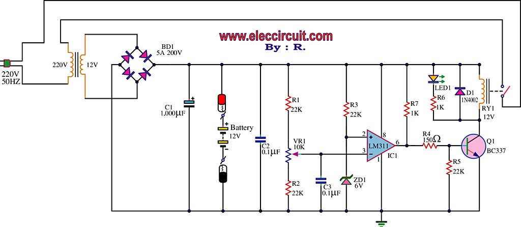
The best 12 Volt battery charger circuit is an automatic system that activates when the battery voltage falls below a specified threshold. This 12 Volt battery charger circuit is designed to efficiently charge lead-acid batteries while ensuring safety and longevity....
The 1N4001 is a 1 Amp silicon rectifier with a voltage range of 50 to 1000 volts. It features guaranteed high-temperature soldering, high current capability, a diffused junction, low reverse leakage, and utilizes a void-free molded plastic technique for...
This sawtooth wave generator provides a sweep signal at output 1 and a synchronization output at output 2, which activates when the sawtooth wave returns to its starting point. The frequency of the sawtooth wave signal is calculated using...

The MC33411 900 MHz Analog Cordless Phone Baseband system is designed to meet the specifications of a 900 MHz Analog cordless telephone system. It includes three Phase-Locked Loops (PLLs). Two of these PLLs are intended for use with external...
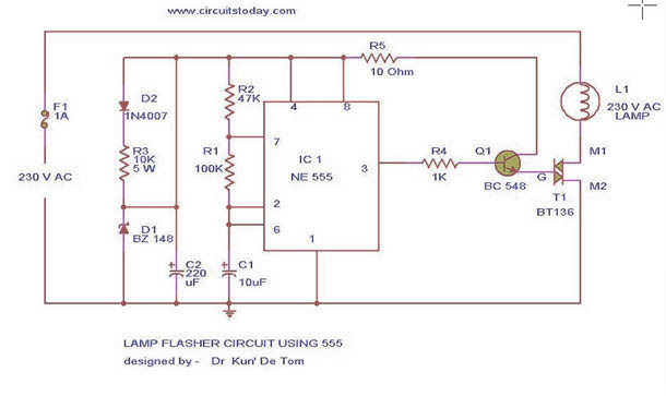
This circuit diagram represents a lamp flasher powered by mains electricity. It is capable of flashing lamps with a maximum power of 200 Watts at user-defined rates. The NE555 integrated circuit is configured as an astable multivibrator, generating the...
This is a very simple 555 timer circuit that serves as a straightforward theft deterrent, which may be just as effective. The idea is to have a flashing red LED indicate that your car is protected. This device can...