
RS-232 surge protection

Overvoltage protection circuits are essential in safeguarding sensitive electronic components, particularly in data communication applications such as RS-232C serial ports. The primary function of these circuits is to prevent excessive voltage levels from damaging the connected devices.
A typical overvoltage protection circuit may include components such as zener diodes, transient voltage suppressors (TVS), and series resistors. Zener diodes can be employed to clamp the voltage to a specific level, thereby preventing it from exceeding the maximum ratings of the connected components. The zener diode should be selected based on the maximum allowable voltage for the device being protected.
Transient voltage suppressors offer rapid response to voltage spikes, making them suitable for protecting against transient overvoltages. In addition, series resistors can be included to limit the current flowing through the circuit during an overvoltage event, providing an additional layer of protection.
The construction of the circuit is equally important. Proper layout techniques, such as minimizing trace lengths and ensuring adequate grounding, can significantly enhance the effectiveness of the overvoltage protection. Components should be positioned to minimize inductance and capacitance, which can affect the circuit’s response time.
For those who require a higher level of reliability and performance, commercial overvoltage protection units from reputable manufacturers are recommended. These units are designed to meet stringent standards and are tested for performance, providing peace of mind in critical applications.
In summary, implementing an effective overvoltage protection circuit involves careful selection of components and attention to construction details. By doing so, the longevity and reliability of sensitive electronic devices, particularly in communication applications, can be significantly improved.The following circuit are provded here to give your idea how the overvoltage protecton circuits really work and how you can easily add some protection to your circuits. To make theose circuit really effective need careful component choosing and good construction. For best performace I recommend using commercial units from realiable data communication product manufacturers.
RS-232C serial port lines are quite prone to be damaged by overvoltages. The damaged to computer serial ports have become more and more expensive to replace because of higher intergaration: usually you have to buy new motherboard if one serial port in it 🔗 External reference
Related Circuits
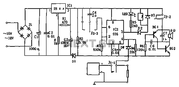
Circuit diagram for a DC power supply protection circuit. The device includes a buck rectifier power supply, a monostable delay circuit, a relay control circuit, and an audio feedback oscillation circuit. The entire circuit operates with a DC voltage...
Crowbar circuits are named for their function, which resembles dropping a crowbar across electrical terminals. They are employed only as a last resort and should only be used where the connected circuit is adequately fused or includes other protective...

To prevent deep discharge that can damage or shorten the life of a rechargeable battery, it is essential to disconnect its load before the battery is completely discharged. The circuit protects against AC line disturbances by switching off the...
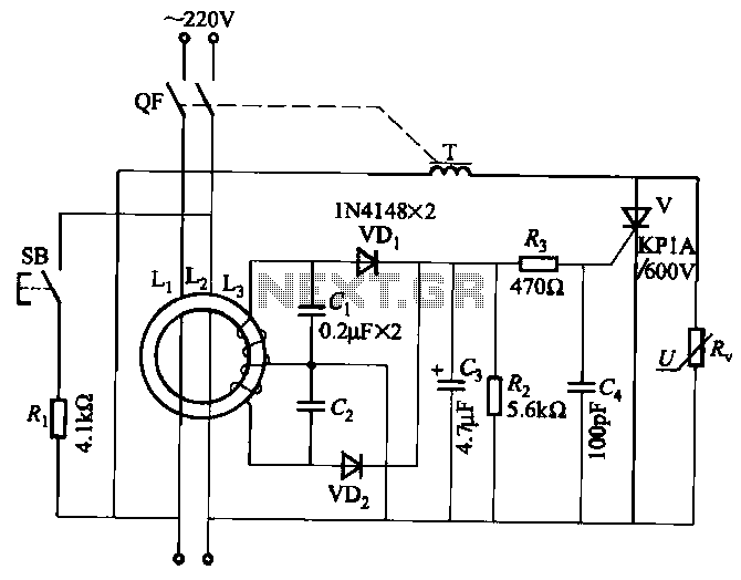
JBD3-10 leakage protection circuit The JBD3-10 leakage protection circuit is designed to detect and mitigate leakage currents in electrical systems, enhancing safety and preventing potential hazards. This circuit employs a differential current transformer that continuously monitors the current flowing through...
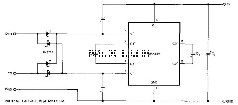
The circuit demonstrates a method for powering CMOS integrated circuits (ICs) using RS-232C lines. The MAX680 is typically employed to generate a voltage equal to ±2 Vcc. This circuit operates in the opposite manner, accepting ±10.5 to ±12V from...
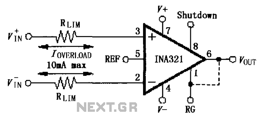
The input current protection circuit for the INA321/322 is illustrated. The INA321/322 features input terminal electrostatic discharge (ESD) protection diodes that become conductive when the input voltage exceeds the supply voltage by 500mV. The protection diodes will conduct, and...