
RS232 to USB Converter

The RS232 to USB converter is an essential interface device that allows communication between devices with RS232 serial ports and modern computers that utilize USB ports. This converter is particularly useful in scenarios where older serial devices need to be integrated into contemporary computing environments, enabling data transfer and device control.
The circuit typically comprises several key components: a USB connector, an RS232 connector, and a level-shifting integrated circuit (IC) that facilitates the conversion between the two signal types. The USB connector interfaces with the host computer, while the RS232 connector connects to the serial device. The level-shifting IC, such as the MAX232 or similar, converts the voltage levels of the RS232 signals (which can range from -12V to +12V) to the 0V to +5V levels that USB devices require.
In operation, the RS232 signals are received by the level-shifting IC, which translates them into a format compatible with USB communication protocols. Conversely, signals from the USB side are converted back into RS232 format for transmission to the serial device. This bidirectional communication allows for seamless data transfer and control commands between the two interfaces.
Additionally, the converter may include features such as signal conditioning, which helps in minimizing noise and ensuring reliable data transmission, as well as LED indicators to show the status of the connection and data transfer activity. This device is widely used in various applications, including industrial automation, legacy device interfacing, and data logging systems, making it a versatile tool in the field of electronics.[caption id=attachment_45 align=alignnone width=500 caption=Serial RS232 to USB][/caption] This is simple RS232 Serial to USB Converter that. 🔗 External reference
Related Circuits
On the DMX line side, an XLR connector should be utilized, either a 3-pin or 5-pin connector. The pins in an XLR connector are typically numbered, eliminating the need for a visual reference. In the case of the 5-pin...
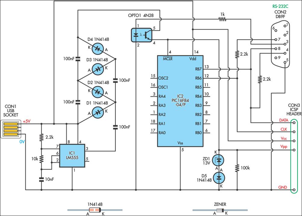
This simple circuit can be used to program the PIC16F84 and similar "flash memory" type parts. It utilizes a 555 timer IC to generate the programming voltage from a +5V rail, allowing the circuit to be powered from a...
A substation capable of consuming 100 MVA with 375 kVA, 60 Hz input and 132 kV at 50 Hz using the same power. The challenge is to convert the 60 Hz input to 50 Hz, including a wiring diagram. To...
This circuit facilitates a VGA to SCART connection, converting VGA signals into RGB and composite sync signals suitable for a TV via a SCART connector. The RGB components—Red, Green, and Blue—output from the VGA card are already at the...

The main ΣΔ loop operates in steady state and is fully controlled by summing comparator Q2. This comparator amplifies the ripples of the sensed inductor current and output voltage with gains KI and KV, respectively, to generate an internal...

This circuit, based on the 555 timer, functions as a voltmeter and an analog-to-digital converter, converting analog input voltage into digital output pulses. The 555 timer is a versatile integrated circuit commonly used for timing, oscillation, and pulse generation applications....