
schematic of lenovo e317

The analog baseband digital circuit encompasses a variety of interfaces and components essential for the operation of modern electronic systems. The EMI (Electromagnetic Interference) interface is crucial for ensuring that the circuit operates without interference from external electromagnetic sources, thereby maintaining signal integrity. The BPI (Bus Protocol Interface) bus facilitates communication between different components, allowing for efficient data transfer and control signals.
The JTAG (Joint Test Action Group) interface is employed for testing and debugging purposes, enabling access to the internal states of the circuit and providing a means to program devices. The LCD (Liquid Crystal Display) interface allows for visual output, while the keypad interface enables user input, both of which are vital for user interaction with the device.
UART (Universal Asynchronous Receiver-Transmitter) is a standard communication protocol used for asynchronous serial communication, providing a reliable method for data exchange. The MINT (Microcontroller Interface) and GPIO (General Purpose Input/Output) pins offer additional flexibility in interfacing with various peripherals.
The MCP (Microchip Technology) keypad is utilized for enhanced user input capabilities, and audio components are integrated for sound processing. RF (Radio Frequency) elements are included for wireless communication, while I/O connectors provide physical connections to external devices.
Power management is addressed through power cones, which regulate voltage levels, and the battery charging circuit ensures efficient power supply management. The analog LED driver controls the brightness of LEDs, and RF control circuitry manages radio frequency signals. The IOTA (Input/Output Asynchronous Transfer Architecture) enhances data handling capabilities.
Audio codecs are incorporated for digital audio processing, enabling high-quality sound reproduction. The MCU (Microcontroller Unit) serves as the central processing unit, coordinating all operations within the circuit. SIM level shifters are essential for interfacing with different voltage levels, ensuring compatibility with various components. Finally, voltage regulators maintain stable power supply levels for the entire circuit, ensuring reliable operation across all components.Analog baseband digital circuit table of contents:, Emi interface, BPI bus, Jtag, LCD interface, keypad, UART, mint, Gpio, and Mcp keypad, audio, RF, I/O connectorPower cones, serial time, battery charging and analog, Led driver, RF control, Jtag, iota, audio codecs, MCU, SIM level shifters, voltage regulator 🔗 External reference
Related Circuits
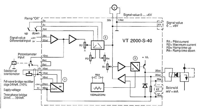
The function is to adjust the time constant associated with a capacitor, thereby influencing the ramp time. The components involved include a transistor, capacitor, and resistor. The circuit described is designed to modify the time constant in an RC (resistor-capacitor)...
PowerMan UPS/Inverters manufactures uninterruptible power supplies and voltage regulators. The business was founded in 1993 and was involved in distribution prior to the year 2000. PowerMan specializes in providing reliable power solutions, including uninterruptible power supplies (UPS) and voltage regulators,...
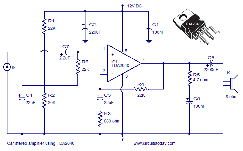
A car stereo amplifier circuit utilizing the TDA2040 is presented here. The TDA2040 is a monolithic integrated audio amplifier that functions in Class AB mode. This integrated circuit features built-in short circuit protection and thermal shutdown capabilities, and it...
This USB circuit utilizes an integrated circuit (IC) to convert digital voice data into an analog format, making it suitable for headphone use. Additionally, the output can be amplified through a power amplifier, allowing the sound to be played...
To construct the circuit, follow the provided schematic. If assistance is required, do not hesitate to reach out for support. If there are difficulties in identifying the components... To build the circuit effectively, it is essential to adhere closely to...
This software is highly effective, user-friendly, and enjoyable to utilize. It features an extensive library of symbols and includes a library editor for creating custom symbols. All drawings were completed before any soldering commenced, instilling confidence that all elements...