
schematics Control speed of Nidec fan
To achieve variable speed control for the Nidec TA450DC fan, a pulse-width modulation (PWM) controller can be employed. This method allows for effective speed regulation while maintaining low noise levels. The fan operates on a 12V DC supply, and the red wire is connected to the positive terminal, while the black wire connects to ground. The blue and yellow wires typically serve as a tachometer output and a PWM control input, respectively.
A suitable approach involves using a PWM speed controller circuit, which can be constructed using a transistor or a dedicated PWM controller IC. The PWM signal modulates the voltage supplied to the fan, effectively controlling its speed. The circuit can be designed with a potentiometer (variable resistor) that acts as the speed control knob. The potentiometer is connected in such a way that it adjusts the duty cycle of the PWM signal based on its position.
The wiring configuration would include connecting the potentiometer to the control input (yellow wire) of the fan. The PWM circuit's output will be fed into the yellow wire, while the blue wire can be left unconnected if it is solely for tachometer feedback, which may not be necessary for basic speed control.
For assembly, a small circuit board can be used to house the components. The PWM circuit will require a power source, which can be derived from the same 12V supply used to power the fan. The transistor or PWM controller IC can be mounted on the board, with the potentiometer accessible from the exterior for user adjustment.
In summary, the desired outcome is to create a simple yet effective PWM speed control circuit that utilizes a potentiometer to adjust the fan speed smoothly from minimum to maximum, while ensuring that the fan operates quietly and efficiently within the wooden cabinet.I have a Nidec TA450DC B35502-35 fan which I`ve installed in a large wooden cabinet where my computer and other electronics sit. This cabinet of course gets hot from all the electronics inside of it. The fan forces air in from the room and goes out through openings in the top of the cabinet. This fan has 4 wires: red (+12v), black (ground), and then blue and yellow. I`m using only red and black to give the fan full 12v power. The problem is since it`s at max speed, it is way too loud. I have a simple toggle switch to turn it on and off. What I would like to do is replace the toggle switch with a knob to adjust the speed. I don`t know how to use the other two wires to control the speed. What kind of knob do I need to get, and how should I wire it The minimum setting of the knob should feed the fan with its minimum required power to spin at the lowest speed possible, and the highest setting should spin it at full possible speed. I don`t have any problem with soldering a small circuit board together for this project, I just have no idea what schematic I need to put together.
I`ve played with electronics and their components all my life but don`t know nearly enough to even begin understanding how to accomplish this. It should be simple, right Should I be using one or both of the additional wires for this, or should I use some method of adjusting the voltage
🔗 External reference
Related Circuits
To achieve optimal audio reproduction at varying listening levels, it is essential to adjust tone control settings to align with the established characteristics of human auditory perception. The sensitivity of the human ear changes non-linearly across the entire audible...
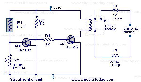
The circuit diagram of an Automatic Street Light Controller Circuit is explained in this post. The Automatic Street Light Controller Circuit is designed to automatically turn on street lights at dusk and turn them off at dawn. This functionality is...

This device acts as a variable speed control for the heater blower in a car. It takes its power directly from the existing wiring and connects with just 2 wires. It will also work for any 12 volt device...
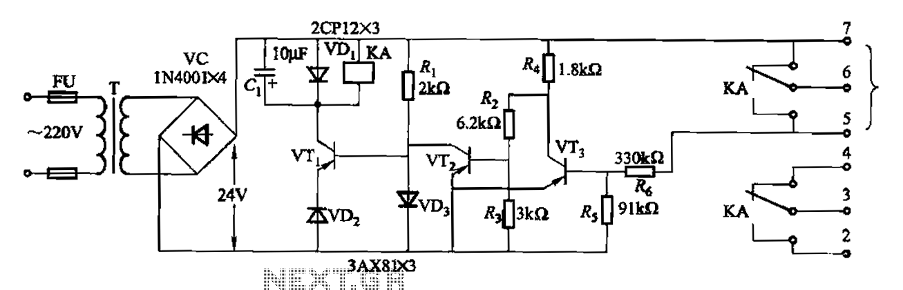
Another JYB type liquid level controller internal circuit is shown. This circuit employs a Schmitt trigger configuration, enhancing the reliability of the action level controller. The JYB type liquid level controller utilizes a Schmitt trigger circuit composed of transistors VT2...
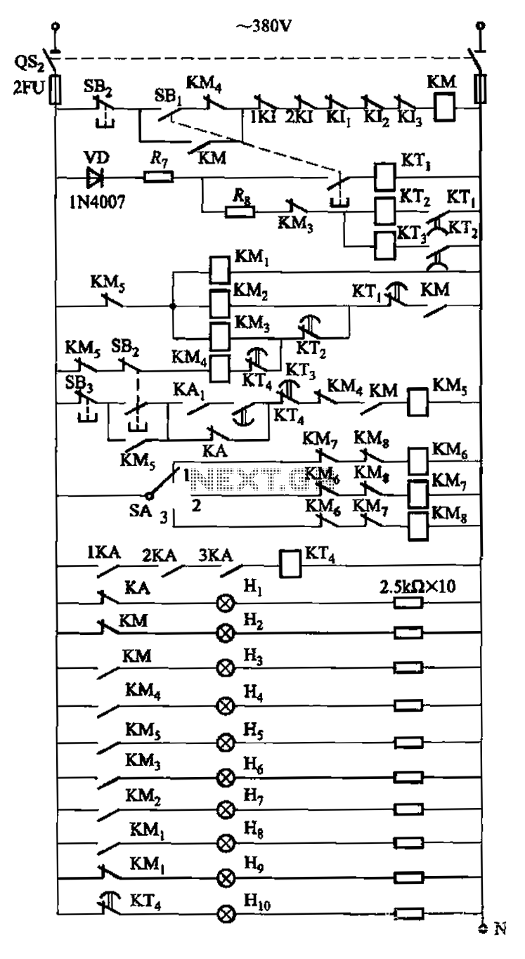
The circuit is illustrated. A motor utilizes series resistance in the rotor winding for starting. The drawing includes electrical velocity off the relay KIi ~ KI3 for motor short circuit protection and overcurrent. Additionally, relays 1KI and 2KI provide...
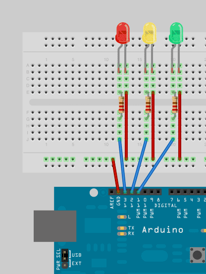
To enhance Arduino programming skills, developing a traffic light controller serves as an excellent practice project. The traffic light controller project involves designing a circuit that simulates the operation of a traffic light system, typically consisting of red, yellow, and...