
thermostat for 1kw space heater scr controlled

The described circuit employs a heating element that operates under the control of two SCRs configured in a back-to-back arrangement, allowing for effective control of the heating process during both halves of the AC waveform. The use of SCRs is advantageous due to their ability to handle high current loads, making them suitable for applications such as heating elements in industrial or domestic settings.
The pulse transformer plays a critical role in this circuit by providing the necessary isolation and triggering mechanism for the SCRs. The three identical windings serve distinct functions: two windings are responsible for generating the trigger pulses that activate the SCRs, while the third winding is utilized to drive a pair of PNP transistors. These transistors are configured to alternate the supply of pulses to the transformer, ensuring that the SCRs are triggered appropriately at the beginning of each AC half-cycle.
The control strategy implemented in this circuit is particularly noteworthy. By applying trigger pulses to both SCRs at the commencement of each AC half-cycle, the circuit ensures that only one SCR will conduct based on the AC polarity. This selective conduction is essential for maintaining the correct direction of current flow through the heating element, thereby optimizing the heating efficiency and protecting the components from potential damage due to reverse polarity.
In summary, this circuit design effectively utilizes SCRs and a pulse transformer to control a heating element, demonstrating a reliable method for managing AC power in heating applications. The alternating pulse supply from the PNP transistors guarantees that the SCRs are activated in a synchronized manner with the AC signal, providing efficient and safe operation of the heating element.The heater element (not shown) is connected in series with two back to back 16 amp SCRs (not shown) which are controlled with a small pulse transformer. The pulse transformer has 3 identical windings, two of which are used to supply trigger pulses to the SCRs, and the third winding is connected to a PNP transistor pair that alternately supply pulses to the transformer at the beginning of each AC half cycle.
The trigger pulses are applied to both SCRs near the beginning of each AC half cycle but only one conducts depending on the AC polarity.. 🔗 External reference
Related Circuits

The thermostat electric circuit operates as depicted in the figure. It has three settings: off, low power (Lo), and high power (Peru HL). When the DIP switch SA is set to the Lo position, 220V AC is directed through...
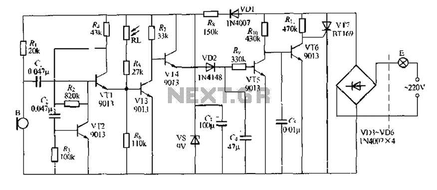
This circuit design is a sound and light control delay switch for staircase walkway lighting, featuring high voice sensitivity. In the evening, when someone walks on the stairs, their footsteps activate the electronic meter, turning on the lights. If...
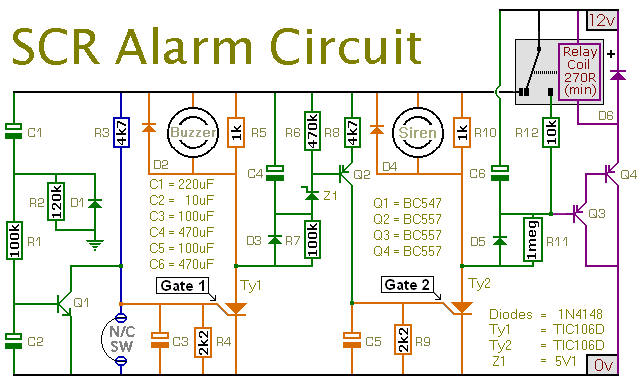
This is a simple SCR-based burglar alarm circuit. Its features include automatic exit and entry delays, along with a timed bell cut-off and reset. It is designed to be used with standard types of normally-closed input devices such as...
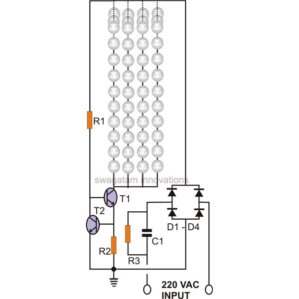
The circuit of a current-controlled LED tube light employs high-voltage transistors to implement the necessary current control operation based on a fundamental principle. A resistor (R2) is utilized to convert the increasing current into a voltage across itself. This...
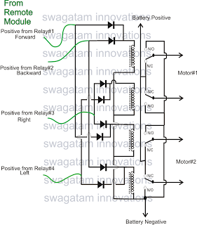
The market is filled with high-end remote-controlled toy cars; however, for hobbyists, creating one at home can be a unique experience. The following article explains how to configure a simple remote-controlled toy car using a pre-made 4-relay remote control...
A discussion took place on synth-diy regarding the challenges of constructing a voltage-controlled oscillator with a sawtooth wave output, where the duty cycle (the ratio of ramp-up time to ramp-down time) can be adjusted using a separate control voltage....