
Combination Lock Circuit
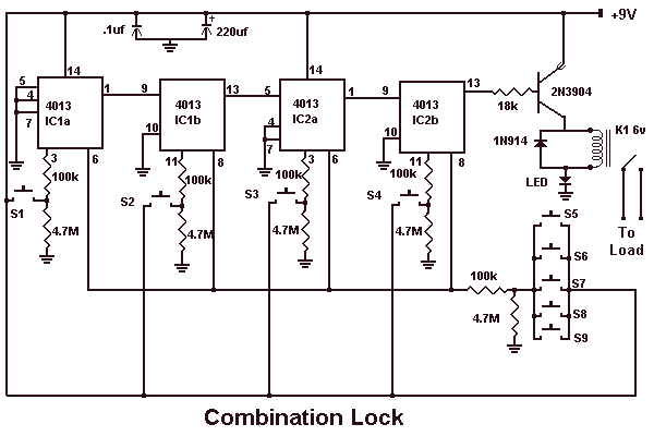
The described circuit functions as a sequential lock mechanism, utilizing a series of momentary push-button switches (S1, S2, S3, S4) to control a load (K1). The operational principle is based on the requirement to press the switches in a specific order to activate the lock.
The circuit can be constructed using a microcontroller or a simple logic circuit with flip-flops to track the correct sequence of inputs. Each momentary switch is connected to an input pin of the microcontroller or to the clock input of a flip-flop. When a switch is pressed, it sends a signal to the circuit, which checks if the input corresponds to the next expected switch in the sequence.
If the correct switch is pressed, the circuit proceeds to the next switch in the sequence. If an incorrect switch is pressed, the circuit resets, requiring the user to start over. This feature can be implemented using a reset mechanism, which can be a simple logic gate configuration or a software routine in a microcontroller.
The wiring of the switches can be arranged in various configurations, allowing for flexibility in the choice of switch combinations. For instance, the switches can be connected in parallel to a common input line, with each switch having a unique identifier in the software or logic circuit.
The load (K1), which could be a solenoid, relay, or any other actuating device, is activated once the complete sequence is successfully entered. To ensure user feedback, the circuit may incorporate LEDs or buzzers to indicate the status of the input sequence, providing visual or auditory cues for correct or incorrect inputs.
Overall, this circuit is a straightforward yet effective implementation of a sequential locking mechanism, suitable for various applications requiring controlled access.This circuit is very basic to build. To open a the lock which is connected to the K1 Load you must press each momentary switch in the correct sequence. The sequence used in this circuit is S1,S2,S3,S4. If any of the other switches are pressed the circuit will reset and you will need to start over. Depending on how you wire the switches, you can use any 4 switch combination. 🔗 External reference
Related Circuits
This circuit is designed for precise centigrade temperature measurement. It features a transmitter section that converts the sensor's output voltage, which is proportional to the measured temperature, into frequency. The output frequency bursts are transmitted through the mains supply...
This is a simple electronic circuit for a clap switch project. It is suitable for beginner electronics learners who enjoy experimenting with new projects. The circuit can turn on or off a 220V electronic device, such as a fan...
The AC contactor DC transformer circuit operates using various types of transformers and AC contactors in a DC application. The AC contactor DC transformer circuit is designed to control and manage electrical power in applications where alternating current (AC) is...
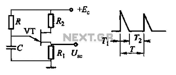
Common non-sinusoidal oscillator circuit, waveform and frequency formula - pulse wave oscillator - blocking oscillator transformer The common non-sinusoidal oscillator circuit is designed to generate pulse waveforms, which are characterized by their square or rectangular shape. These oscillators are...
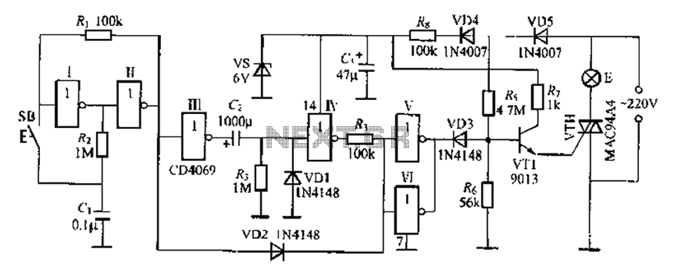
A delay lamp circuit is ideal for bedside tables, featuring a button (SB) that turns the light on and off. If the button is not pressed, the circuit maintains a delay before the light turns off. If the light...

Bicycle tire leak detector circuit schematic. The circuit detects air leaks in car tires caused by sharp objects. It uses a microphone (BM) to capture the sound of escaping air, which is then converted into an electrical signal. This...