
Self switching Power Supply

The described regulated power supply circuit utilizes the LM7805 voltage regulator, which typically provides a fixed output voltage of 5V. However, in this design, a potentiometer (VR1) is employed to adjust the output voltage dynamically. The potentiometer is connected between the common terminal of the LM7805 and ground, allowing the user to vary the resistance. This configuration enables the output voltage to change in response to the potentiometer setting. Specifically, for every 100-ohm increase in the resistance of VR1, the output voltage increases by 1 volt. Consequently, the output voltage can be adjusted within a range of 3.7V to 8.7V, considering the voltage drop of 1.3V across the two diodes (D1 and D2) included in the circuit.
In addition to the variable output feature, the circuit incorporates a load detection mechanism that enhances its efficiency. When no load is connected to the output terminals, the circuit will automatically switch itself off. This function is facilitated by the arrangement of transistors T1 and T2, along with diodes D1 and D2, and capacitor C2. The transistors act as switches that monitor the output current. If the output current falls below a certain threshold (indicating no load), the transistors disable the power supply, thereby reducing power consumption and preventing unnecessary heat generation. This feature is particularly beneficial in battery-powered applications, where energy efficiency is crucial.
The overall design ensures that the regulated power supply circuit is versatile, allowing for adjustable output voltage while also incorporating intelligent load management. The combination of the LM7805 regulator, the variable resistor, and the load detection circuitry makes this power supply suitable for various electronic applications that require a stable and adjustable voltage source.One of the main features of the regulated power supply circuit being presented is that though fixed-voltage regulator LM7805 is used in the circuit, its output voltage is variable. This is achieved by connecting a potentiometer between common terminal of regulator IC and ground. For every 100-ohm increment in the in-circuit value of the resistance of potentiometer VR1, the output voltage increases by 1 volt.
Thus, the output varies from 3.7V to 8.7V (taking into account 1.3-volt drop across diodes D1 and D2). Another important feature of the supply is that it switches itself off when no load is connected across its output terminals. This is achieved with the help of transistors T1 and T2, diodes D1 and D2, and capacitor C2. When a load is connected at the outp 🔗 External reference
Related Circuits
This document outlines a basic circuit designed to power high impedance, high voltage, low current devices such as electroluminescent (EL) backlights and fluorescent tubes. The project originated from the need for a simple yet flexible inverter circuit for an...
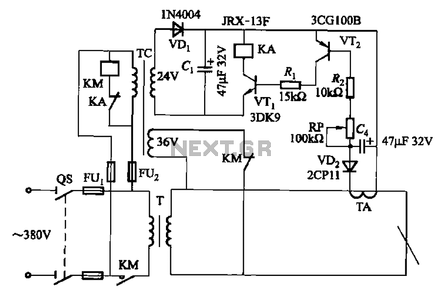
The AC arc welding machine's transistor load path for the power from the second circuit is illustrated. The figure shows a current transformer with a core cross-section of 25 mm². The transformer has a primary winding with a certain...
The objective is to enhance information transmission through the distribution of articles. Please contact us via email at [email protected] within 15 days if there are any issues related to article content, copyright, or other concerns. Prompt action will be...
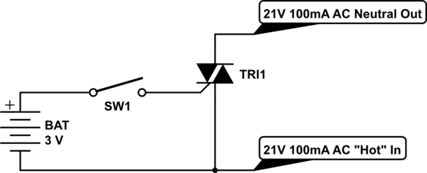
Control a furnace using a 3.3V microcontroller. The furnace operates by connecting a common 21V AC "hot" line to one of two AC "neutral" output lines: Fan and Heat. When connected, they have relatively low current flow, approximately 100mA....
This circuit can be adapted for other regulated and unregulated voltages by using different regulators and batteries. For a 15 Volt regulated supply use two 12 Volt batteries in series and a 7815 regulator. There is a lot of...
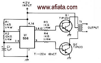
The first section of the 555 timer is configured as an astable oscillator, with R2 and C1 determining the frequency. The output is accessible at pin 5. The second section functions as a phase inverter, with its output available...