
Fiber-optic link

The described analog transmission system for fiber optic applications operates effectively within the frequency range of up to 3 MHz, making it suitable for various optical communication tasks. The system comprises a transmitter and a receiver, where the transmitter utilizes a light-emitting diode (LED) that is typically biased at a constant current of 50 mA. This biasing ensures that the LED operates efficiently, providing a stable light output necessary for reliable data transmission.
The input signal to the transmitter is capacitively coupled, allowing for the modulation of the LED current based on the input voltage, which can range from 0 to 5 V. This modulation capability is crucial as it enables the LED to vary its output current between 0 and 100 mA, effectively encoding the input signal into light pulses for transmission through the fiber optic medium.
On the receiving end, the circuit is designed as a transimpedance amplifier, which is crucial for converting the small photocurrent generated by the photodiode into a measurable output voltage. The photodiode is characterized by a responsivity of 0 A/W, indicating its efficiency in converting light into electrical signals. For an input light power of 1 µW, the photodiode generates a corresponding output signal of 50 mV at the receiver. This voltage output can then be processed further to retrieve the transmitted information.
Overall, this analog transmission system is an essential component in fiber optic communication, facilitating high-frequency data transfer with precise modulation and demodulation capabilities. Its design ensures optimal performance in transmitting and receiving signals over optical fibers.Fiber Optic applications require analog drivers and receivers operating in the megahertz region. This complete analog transmission system is suitable for optical communication applications up to 3 MHz. The transmitter LED is normally biased at 50 mA operating current. The input is capacitively coupled and ranges from 0 to 5 V, modulating the LED current from 0 to 100 mA.
The receiver circuit is configured as a transimpe-danee amplifier The photodiode with 0 amp per watt responsivity generates a 50 mV signal at the receiver output for 1 /iW of light input.
Related Circuits
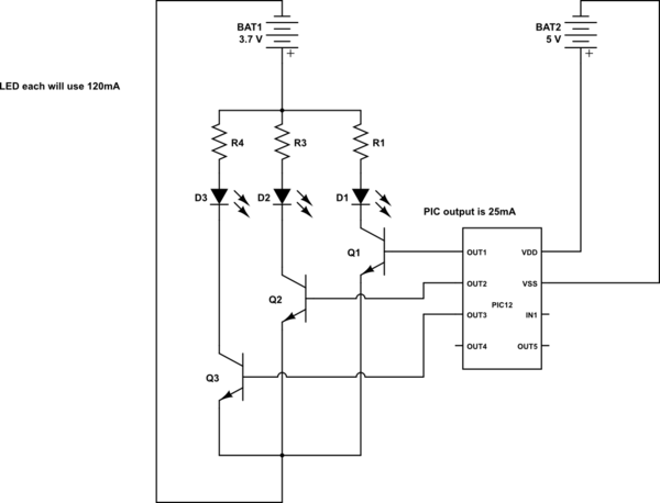
This is a conceptual schema utilizing a PIC12 microcontroller to control the blinking of three LEDs, each exhibiting different blinking patterns. There are several questions that need to be addressed. The circuit design involves a PIC12 microcontroller, which is a...
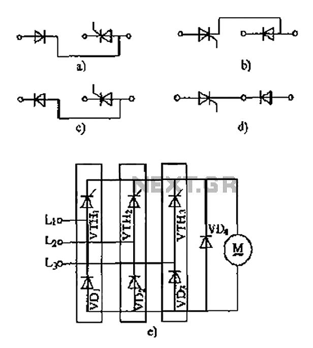
The thyristor linking arm rectifier module is a three-phase half-controlled bridge rectifier circuit. The thyristor-rectifier module linking arm consists of a thyristor and a rectifier diode connected in series or parallel, designed to fulfill specific requirements in power circuits....
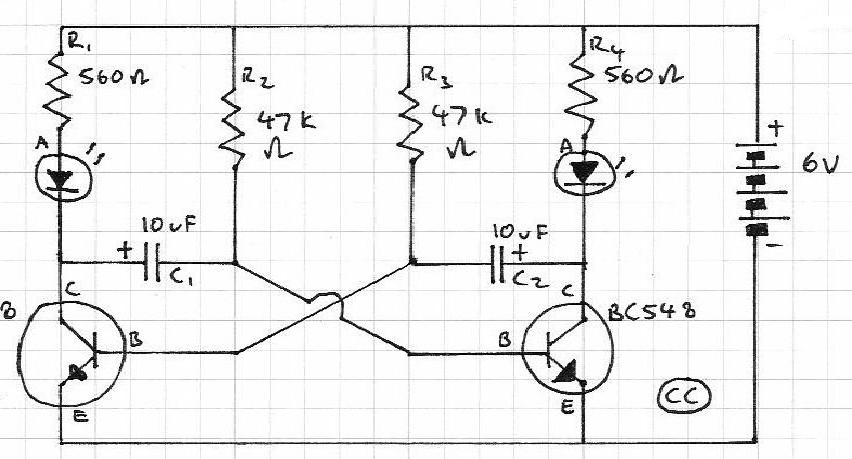
Blinks 2 LEDs in sequence. An explanation of its operation is requested. It is understood that a capacitor charges, causing the LED to turn off, and when it discharges, the LED turns on. However, clarification on the purpose of...
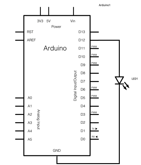
The schematic for this project consists of adding a single 5mm LED to one digital output port on the Arduino. The main components in the schematic include the Arduino Uno, a 5mm LED, and a USB cable. The left...
The circuit allows a precision regulated drive current to be set to drive an LED, and in response to a TTL level signal, the LED is switched on and off with rise and fall times of less than 500...
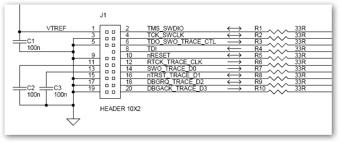
This interface schematic illustrates the JTAG, Serial Wire, and ETM interface circuits of ULINKpro. It can be utilized to analyze potential issues with the target hardware. The schematic represents the interconnections and functionalities of the JTAG (Joint Test Action...