
Serial Cable for Casio Digital Cameras

The described circuit functions as a level shifter, specifically designed to interface between the RS-232 communication standard and the CMOS logic levels utilized by the Casio QV-200 digital camera. The RS-232 standard operates at voltage levels typically ranging from +3 to +15 volts for a logical '0' and -3 to -15 volts for a logical '1', while CMOS logic levels operate at much lower voltages, commonly around 0 to 5 volts.
The inverting buffer/converter circuit is implemented using a suitable integrated circuit (IC) such as the 74HC14, which is a hex inverter with Schmitt-trigger inputs. This IC allows for reliable operation at the lower CMOS voltage levels while also providing the necessary inversion of the signal. The circuit design includes a series of resistors and capacitors to filter and stabilize the signal, ensuring that noise is minimized during the level conversion process.
The physical construction of the circuit within the hood of a DB9F connector is advantageous for maintaining a compact design while providing easy connectivity to the camera. The DB9F connector serves as a standard interface for serial communication, allowing the cable to be used with various devices that support RS-232 communication. Proper pin assignments must be adhered to, ensuring that the transmit (TX) and receive (RX) lines are correctly connected to facilitate data transmission between the camera and the host device.
This level-shifting cable effectively enables communication between the Casio QV-200 and other RS-232 compatible devices, thus enhancing the functionality and versatility of the camera without requiring modifications to the internal circuitry of the device itself.I built this cable for my Casio QV-200 digital camera, it should work for many Casio models. It`s basically a inverting buffer/converter to/from RS-232 voltage levels from/to CMOS levels. Why Casio didn`t put this inside the camera like everyone else does is beyond me. I built the circuit inside the hood of the DB9F connector. 🔗 External reference
Related Circuits
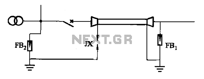
A 6-35kV cable line substation includes a lightning protection system, which is illustrated in Figure (a). This system protects the access lines; for single-core cables, the end of the metal sheath must adhere to the ground clearance protection standards,...
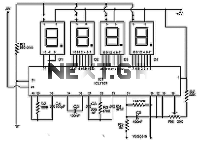
The circuit presented is a highly effective and precise digital voltmeter with an LED display utilizing the ICL7107 from Intersil. The ICL7107 is a high-performance, low-power, 3.5-digit analog-to-digital converter (ADC). This integrated circuit (IC) incorporates internal components such as...
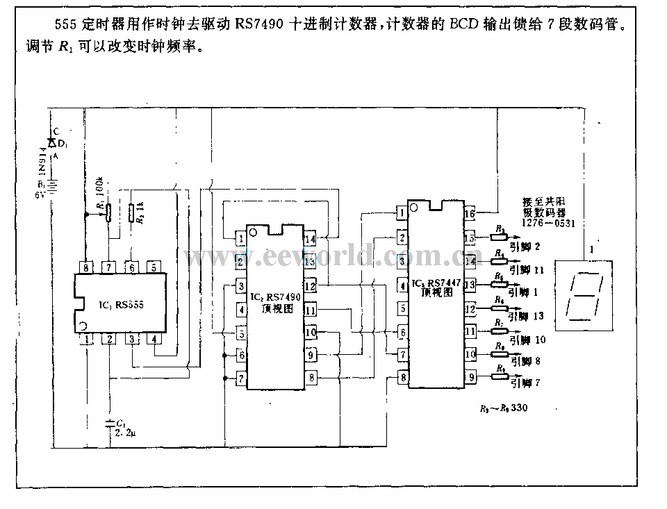
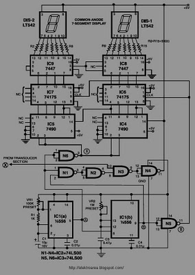
The 555 timer is utilized as a clock source to drive the RS7490 decimal counter, providing a BCD output to a 7-segment LED display. The clock frequency can be adjusted by changing the value of resistor R1. The circuit operates...
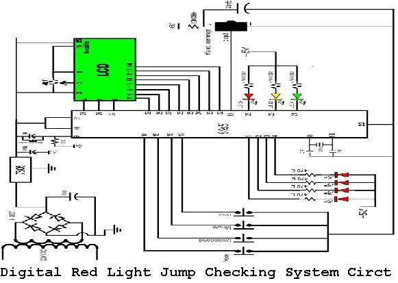
A digital red light jump checking system with an RF transmitter. This project allows for the tracking of vehicles that run red lights by capturing their license plate numbers and the time of the violation. The digital red light jump...
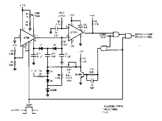
The simple 4-digit converter circuit has an output count of 1, designed to operate within a frequency range of f-IMHz to 10.000. All diodes used in the circuit are IN4146, and the capacitors are made of `POLYSTYRENE` NPO. The...
This circuit is designed to display the speed of a vehicle in kilometers per hour (km/h). An opaque disc is mounted on the spindle connected to the front wheel of the vehicle. The disc features evenly spaced holes along...