
Servo System

other serves as the output. What we are going to do here is to make a remote-controlled potentiometer that repeats the setting of the control potentiometer. This is a typical feedback system, but since it involves a mechanical element, it is called aservomechanism, orservo, for short.
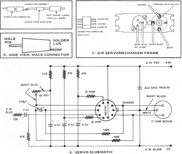
The output could be the shaft position, as well as the electrical output of the controlled potentiometer. In fact, the output of most servos is mechanical. The motor pot consists of a small DC motor, gearing that drives the sliders, the support for the potentiometer resistances, and a shaft.
The connections are shown at the right. We are looking at the motor end; the shaft is at the other end. It is slightly disappointing that the potentiometers are Siamese twins, so they are not completely independent, but that is little matter for our purposes. A clockwise rotation of the shaft, looking from the shaft end, increases the resistance between the common end and the sliders.
A voltage applied to the motor terminals with the marked polarity turns the shaft anticlockwise, bringing the sliders toward the common ends. The motor requires a little more than 2 V to begin turning, so that 5 V is a reasonable maximum. The motor draws about 30 mA or a bit more. There are two connection pins (not shown) on the shaft side of the potentiometer connections that light a red LED that shines through the hole in the shaft.
As you face the shaft, the anode is at the right. Pins 1 and 8 appear to be connected to nothing. An elementary servo circuit is shown at the left. The usual op-amp, here an LF411, cannot drive the motor by itself, and must be helped by transistors. The complementary 2N3904 and 2N3906 can do the job nicely, but, of course, any small complementary pair could be used.
The LF411 is used as a comparator here, which is allowed by its common-mode range. The output saturates one direction or the other to drive the motor. With a ±5 V supply, the motor voltage will be between 3. 5 and 4 V, so no further arrangments are necessary. In this simple circuit, the motor is driven one way or the other at full voltage. A more complicated circuit could provide more sophisticated control. This circuit finds the proper position rapidly, following the control potentiometer. It then oscillates on either side of the correct position at a frequency of about 5 Hz. Observe the output voltage of the op-amp with the oscilloscope on the slowest speed sweep. If the feedback has the wrong sign when you test the circuit, simply exchange the connections to the op-amp inputs. The elimination of the hunting is a more challenging problem than would appear at first sight. If the voltage applied to the motor is decreased as the equilibrium position is approached (proportional control), the motor will stop short at some point.
If this is satisfactory, then the problem is solved, but there will be a little annoying hysteresis because of the finite voltage required for movement. If the error signal is integrated (integral control), it will cause the motor to approach a more correct position until the error is zero.
These refinements are not (at this time) within the scope of this exercise, which is to illustrate basic servo control, but are discussed at length in any text on control systems. On my first try, a quick, erroneous understanding of the connections ruined the potentiometer immediately, when it rotated to one limit.
This, however, gave me the opportunity to disassemble the system and find out what it looked like inside, especially to clarify the connections. The LED was discovered in this way, which had been something of a mystery. The gearing is ingenious. A worm gear on the motor drives a spur gear which is connected to a hypoid right-angle drive, with a ring gear with inclined teeth driven by a curious worm gear.
There is a friction connection to the shaft, so that the shaft can be rotated manually. Of course, the motor gear does not reverse. The whole is nicely manufactured, and probably cost considerably more than the $4. 00 it brings as surplus. 🔗 External reference
Related Circuits
The color wheel and motor control are customizable. This system utilizes field-sequential color rather than the "compatible color" introduced later. Following the wiring modifications, further details about the color wheel will be provided. Without the wheel, CBS shows can...

At the core of the CD4-MX is an astable multivibrator, constructed using transistors Q1 and Q2, which drives step-up transformer T1. The output from T1 is rectified by diodes D3 to D6 and utilized to charge capacitor C4. Upon...

The CYB-P51 (Rev A) Prototyping Board is designed as a two-layer board without dedicated power and ground planes. All components, except for the premounted P-51, utilize through-hole technology for ease of probing and part replacement. The board features an...
The security system application and program offers a simple demonstration of the BASIC Serial Interface. By adding only a few door and window switches, a transistor, a siren, and a few lines of BASIC program the interface can become...
Part II of the AAM Commander RC System Article, scanned from the May 1972 edition of American Aircraft Modeler. The AAM Commander RC System is a sophisticated radio control system designed for model aircraft, providing enhanced control and performance for...

The hum noise is produced by an electronic device with improper design. To address this issue, it is essential to identify the source of the hum. This involves checking the grounding, cabling, casing, and other factors that may contribute...