
Signal Conditioner

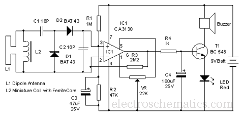
The circuit operates by first receiving an audio signal that may be compromised due to weak signal strength or interference. The phase-locked loop (PLL), designated as U1, plays a crucial role in signal processing by locking onto the frequency of the incoming tone. The frequency detection is achieved through the configuration of resistors R1 and R7 and capacitor C2, which set the PLL's reference frequency. When the PLL successfully detects a tone, it generates a low signal at pin 8.
This low output serves as a control signal that activates tone generator U2. The tone generator is responsible for producing a clean, consistent tone that can replace the original weak signal. The output of U2 can then be used for further processing or directly fed to a speaker or other audio output device. The overall design significantly enhances the clarity of CW signals by filtering out unwanted noise and static, making it a valuable tool for amateur radio operators and audio signal processing applications.
In summary, the circuit effectively recovers and enhances weak CW signals by utilizing a PLL for frequency detection and a tone generator for signal improvement, resulting in clearer audio output. This circuit takes audio from a receiver that might have a weak CW or tone signal and uses a PLL (Ul) to recover the wea k signal. Ul produces a low on receipt of a tone or note of frequency, determined by Rl, R7, and C2. The output of Ul (pin 8) goes low, keys tone generator U2, and produces a new tone. The circuit is useful in cleaning up CW reception in static, noise, etc.
Related Circuits
A block diagram symbol is utilized to represent the PCB schematic on block connection diagrams. The subsequent diagram illustrates the block diagram and the circuit it denotes. A series connection of any number of signal blocks is permissible. To...
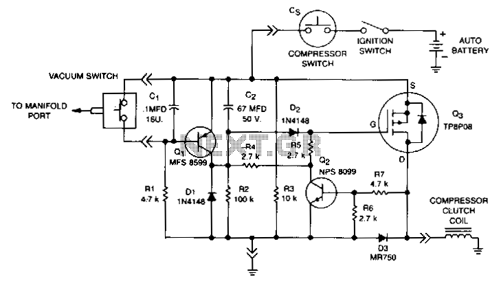
This circuit disables the air conditioner compressor when additional engine power is required. It does so by monitoring the engine vacuum at the intake manifold. If the vacuum drops to 40% of its normal level, the compressor clutch is...
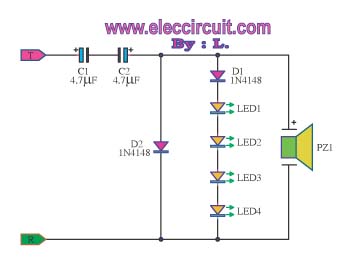
The circuit detects a ringing signal tone and provides both light and sound indicators. It is user-friendly and of good quality, and it does not require a power supply to operate, functioning solely to detect the ringing signal. The described...
This is a pressure sensor signal conditioning circuit. It is a simple and inexpensive circuit due to its small geometry and the use of a straightforward pressure sensor. The pressure sensor signal conditioning circuit is designed to convert the raw...
This function generator IC is specified to work to 20 MHz. So far, this unit works nicely to 50KHz. Since I seldom need signals higher than that, it has taken up a happy home on my workbench and further...
This circuit is designed to detect microwave sources, such as microwave ovens, satellite communication devices, and mobile phones. It provides audio-visual indications when microwaves in the gigahertz band are detected. Microwaves are a form of electromagnetic radiation with frequencies...