
Light Signals
Lighting indicates that the GREEN signal activates only when the block following a specific signal displays a RED signal. The GREEN signal is active when Terminal GI is LOW. The YELLOW or RED input functions similarly to the standard GREEN lighting. The signal circuits can be managed by any device capable of passing at least 1 milliamp current, provided it shares a common connection with the negative terminal of the signal circuit's power supply. The circuit is designed for a 12-volt power supply and is capable of driving light-emitting diodes (LEDs) at approximately 10 milliamps. Different supply voltages and LED currents can be accommodated by adjusting certain resistor values in the circuit. The current-limiting resistor values for the LEDs—R4, R6, and R8—can be modified to achieve the desired brightness for each signal LED. For instance, if the signal LEDs are overly bright, external resistors may be connected at the circuit board's outputs instead of replacing resistors R4, R6, and R8 on the circuit board.
Diodes D1 and D3 at the base circuit of transistors Q1 and Q2 provide an additional voltage drop in the base circuit, allowing the transistors to turn off completely. This diode is unnecessary at the base of Q3. The combined current from the DETECT INPUT of one block and the YELLOW INPUT from the preceding block is approximately 2 milliamps. This low current permits the PNP signal circuit to be directly controlled by optoisolators. More than one block can be managed by a single input device if diodes are employed to isolate block input devices such as occupancy detectors, toggle switches, and computer control systems. Common cathode and common anode connected LEDs can be utilized for different blocks, enabling the use of various home-built and commercial signals simultaneously.
The circuit can be modified to drive two-color, common cathode or common anode connected LEDs to create a Search Light type signal; in this case, diode D2 is omitted from the circuit. The 3 Light Signal Driver circuit can be controlled by numerous types of input devices, including most Block Occupancy Detector designs, toggle switches, and outputs from computer system interface cards. For Block Occupancy Detectors with open collector transistor outputs, the signal circuit and the BOD must share the same power supply and have a common connection at the negative terminal of the power supply. Computer system interface cards generally feature open collector transistor outputs. While the interface card can have its own power supply, it will require a common connection at the negative terminal of both the card's power supply and the signal circuit.
A dispatcher can manage the signals using toggle switches as depicted in the block diagrams. In this scenario, occupancy detectors are not necessary, although they can be used in conjunction with the switches. The subsequent diagram illustrates how diodes can be employed at the BOD inputs of the signals to create more complex signal schemes. The diodes permit separate input devices to control multiple signals while isolating the BODs from one another during standard operation. A potential application for diodes at the BOD inputs is at a rail crossing or interlocking, where tracks lacking the right-of-way would have their signals maintained at RED by the dispatcher until the crossing is clear.
The explanations provided for the circuits on these pages cannot encompass every situation on every layout. Therefore, experimentation may be necessary to achieve the desired results, particularly for circuits such as the "Across Track Infrared Detection" circuits and any other circuit that relies on specific conditions.
The block diagram and circuit schematic outline a modular signal control system for railway applications. The design allows for flexible integration of various input devices, enabling complex signal management while maintaining operational integrity. The use of optoisolators and diodes ensures that signals can be isolated and controlled effectively, providing a robust solution for both home-built and commercial signaling systems. The adaptability of resistor values for LED brightness further enhances the circuit's versatility, making it suitable for a range of operational requirements.A block diagram symbol is used to represent the PCB schematic on block connection diagrams. The following diagram shows the block diagram and the circuit that it represents. Any number of signal blocks can be connected in series. To be able to show all of the aspects the protected track section should be at least four blocks long. APPROACH - Typ e Lighting means that the GREEN signal is on only when the block after a particular signal is showing a RED signal. The Green signal is on when Terminal GI is LOW. The YELLOW or RED input functions are the same as for Normal GREEN lighting. The signal circuits can be controlled by any device that can pass at least 1 milliamp current and shares a common connection with minus terminal of the signal circuit`s power supply.
The circuit is designed for a 12 volt power supply voltage and will drive light emitting diodes at approximately 10 milliamps. Other supply voltages and LED currents can be used by changing the values of certain resistors in the circuit.
The values of the current limiting resistors for the LEDs - R4, R6 and R8 - can be changed to achieve the desired brightness from each signal LED. For example; - If the signal LEDs are too bright, external resistors can be connected at the circuit board`s outputs rather than replacing resistors R4, R6 and R8 on the circuit board.
Diodes D1 and D3 at the base circuit of transistors Q1 and Q2 provide an extra voltage drop in the base circuit that allows the transistors to turn off completely. This diode is not needed at the base of Q3. The combined current from a DETECT INPUT of one block and the YELLOW INPUT from the previous block is about 2 milliamps.
This low current allows the PNP signal circuit to be controlled directly by optoisolators. More than one block can be controlled by a single input device if diodes are used to separate block input devices such as occupancy detectors, toggle switches and computer control systems. Common cathode and common anode connected LEDs can be used for different blocks so that various home built and commercial signals could be used at the same time.
The circuit can be adapted to drive 2 colour, common cathode connected or common anode connected LEDs to make a Search Light type signal. Diode D2 is removed from the circuit for this application. The 3 Light Signal Driver circuit can be controlled by many types of input devices including most Block Occupancy Detectors designs as well as toggle switches and the outputs of computer system interface cards.
For BODs with open collector transistor outputs, the signal circuit and the BOD can use the same power supply and must have a common connection at the minus of the power supply. Computer system interface cards usually have open collector transistor outputs. The interface card can have its own power supply but will need a common connection at the minus of the power supply of the card and the signals circuit.
A dispatcher can control the signals by using toggle switches to control the signals as shown on the block diagrams. In this case no occupancy detectors would be needed but they could be used in conjunction with the switches.
The next diagram shows how diodes can be used at the BOD inputs of the signals to provide more complex signal schemes. The diodes allow separate input devices to control more than one signal while isolating the BODs from each other during normal operation.
A possible use for diodes at the BOD inputs is at a rail crossing or interlocking where tracks that do not have the right-of-way would have their signals held at RED by the dispatcher until the crossing is clear. The explanations for the circuits on these pages cannot hope to cover every situation on every layout.
For this reason be prepared to do some experimenting to get the results you want. This is especially true of circuits such as the "Across Track Infrared Detection" circuits and any other circuit that relies 🔗 External reference
Related Circuits
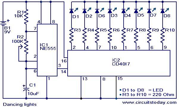
This is a simple dancing light circuit that utilizes the NE555 (IC1) and CD4017 (IC2) integrated circuits. IC1 is configured as an astable multivibrator to generate clock pulses for the CD4017. Each clock pulse received at the clock input...
The following circuit illustrates the use of the AD8531 integrated circuit for the automatic control of LCD panel backlighting. Features include the ability to compensate for aging effects. The AD8531 is a precision operational amplifier that is well-suited for applications...
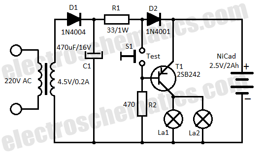
This low-cost automatic emergency lighting circuit activates a lamp during power failures. It is powered by a NiCad battery that is charged by the mains. The automatic emergency lighting circuit is designed to provide illumination during unexpected power outages. The...
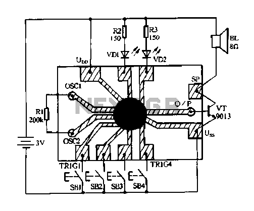
Constantly changing light and sound analog controller circuit 04 The circuit designated as the "Constantly Changing Light and Sound Analog Controller Circuit 04" is designed to modulate both light and sound outputs in a dynamic manner. This type of...
This circuit gives a low-level output when sufficient lighting is present, functioning as a light detector. It can issue a command to turn on lights when darkness falls. Its output is compatible with TTL levels, providing a low logic...
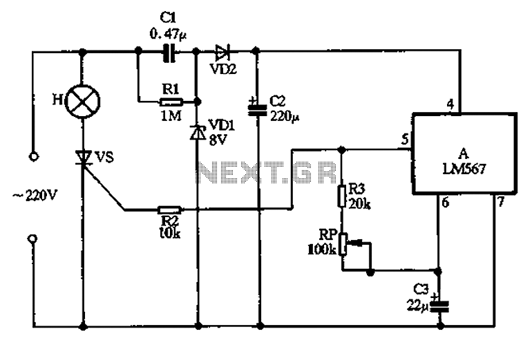
Cl, VDI, VD2, C2 form a simple capacitive step-down voltage regulator circuit with a rectifier output providing approximately 8V DC voltage for the LM567. A 5.6-foot manifold is connected. Resistors R3, RP, and capacitor C3 create an ultra-low frequency...