
Simple but reliable car battery tester

The LM3914 is a bar graph/LED dot display driver that can drive up to ten LEDs in either a bar or dot mode, providing a visual representation of the input voltage level. The IC operates within a voltage range of 4V to 12V, making it versatile for various applications. The input voltage is applied to the reference pin, and the output pins are connected to the LEDs. The internal voltage reference allows the LM3914 to scale the input voltage to the LED outputs effectively.
In a typical application circuit, the input voltage is fed into the LM3914 through a resistor, which sets the current for the LEDs. The output can be configured to operate in either a dot mode, where only one LED lights up at the input voltage level, or a bar mode, where multiple LEDs light up in succession to indicate the level. This feature can be particularly useful in applications such as battery level indicators, audio level meters, or any system where visual feedback of voltage levels is required.
To enhance the functionality, external components such as potentiometers can be added to adjust the reference voltage, allowing for calibration of the voltage range displayed. Additionally, capacitors may be included for noise filtering to ensure stable operation in environments with electrical noise.
The LM3914 is ideal for educational projects and prototypes due to its ease of use and minimal required components, making it a valuable component in various electronic designs.This circuit uses the popular and easy to find LM3914 IC. This IC is very simple to drive, needs no voltage regulators (it has a built in voltage regulator) and can be powered from almost every source 🔗 External reference
Related Circuits
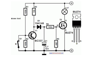
Most cars do not have delayed interior lights. The circuit presented can rectify this issue. It gradually switches the interior lights of a car on and off. The described circuit addresses a common limitation in many automotive lighting systems by...
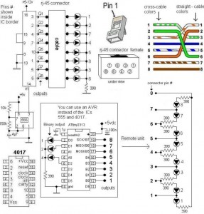
A LAN tester circuit diagram is presented in two designs. The first design utilizes a timer IC 555 and a decade counter 4017. The second design employs a microcontroller ATtiny2313. The first design of the LAN tester circuit incorporates the...
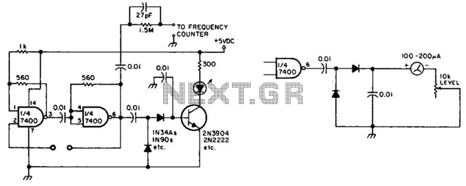
This circuit checks a crystal for activity. Two sections of a 7400 IC act as an oscillator, and its output is rectified to drive an NPN transistor that switches an LED. In an alternative configuration, a meter replaces the...
Figure 1 shows the circuit. A major change from all of the designs from that era is the speaker coupling capacitor - 1000uF (for a -3dB of 20Hz and a 8 Ohm load) was the most common value. This is...
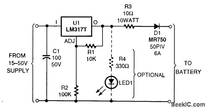
The circuit is based on an LM317T adjustable voltage regulator. The output voltage (VOUT) is defined by the formula VOUT = 1.25 (1 + R2/R1). A 10-kΩ resistor is selected for R1 and a 100-kΩ resistor for R2, allowing...
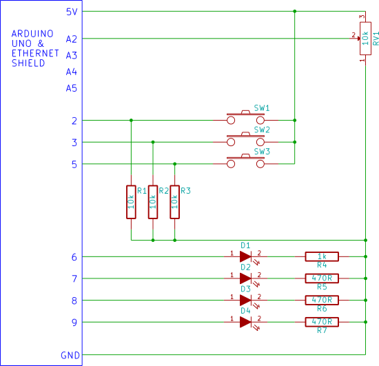
Input and output (I/O) on the Arduino web server using the SD card. Arduino inputs (analog inputs, switches) are displayed on a web page. Arduino outputs (LEDs) are controlled from a web page. Uses Ajax for flicker-free loading. The described...