
Simple color organ

The described circuit utilizes a transformer, referred to as Tl, which serves as a matching device for various transistor types with impedance ratings ranging from 500/500 ohms to 2500/2500 ohms. This flexibility allows for compatibility with a range of audio amplifiers and ensures optimal performance based on the specific requirements of the application.
In the circuit, it is crucial to note that no connections from the silicon-controlled rectifier (SCR) or any associated components are connected to ground. This design choice enhances safety by preventing any potential ground loops that could introduce noise or create hazardous conditions. The circuit operates with a 117-V line voltage, which is standard in many regions, ensuring that the amplifier functions correctly without exceeding voltage ratings.
To facilitate user adjustments, a potentiometer, designated as Rl, is included in the design. Initially, this potentiometer should be set to the "off" position. Following this, the amplifier's volume control can be adjusted to achieve a comfortable listening level. This step is essential to establish a baseline before fine-tuning the system.
After achieving the desired volume level, the next step involves adjusting the potentiometer Rl. The goal of this adjustment is to synchronize the operation of a connected lamp with the audio signal, specifically to make the lamp throb in rhythm with the beat of the music. This visual feedback can enhance the listening experience, providing an engaging multimedia effect that responds to the audio output. Care should be taken during this adjustment to ensure that the lamp's response is not overly sensitive, which could lead to flickering or an unstable visual effect.
Overall, this circuit design emphasizes safety, flexibility, and user engagement, making it suitable for various audio applications where visual feedback is desired.Transformer Tl can be any matching transistor type in the range of 500/500 to 2500/2500 ohms. No connections from the SCR or its components are connected to ground. For safety's sake, keep the 117-V line voltage from the amplifier connections— that is the reason for using Tl. To adjust, set potentiometer Rl "off" and adjust the amplifier volume control for a normal listening level.
Then adjust the potentiometer until the lamp starts to throb in step with the beat.
Related Circuits
this is a very easy circuit to build - all parts can be found at the local electronics shop. The described circuit is characterized by its simplicity and accessibility, making it an ideal project for beginners or those looking to...
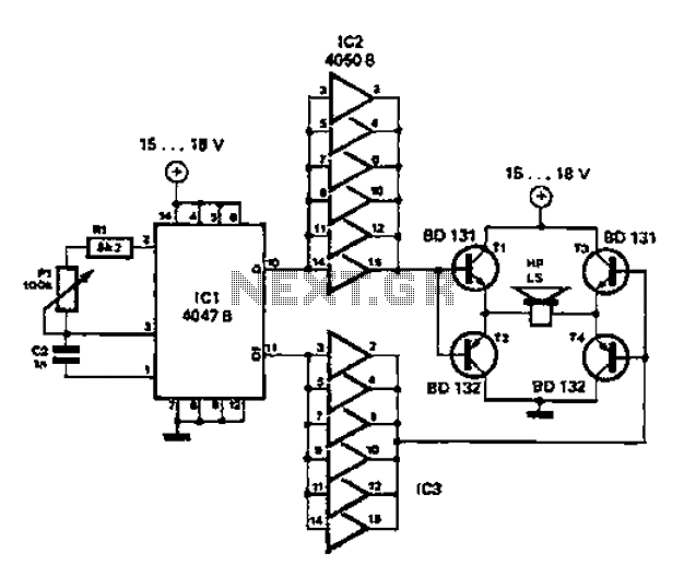
A low-cost and straightforward repellent circuit can be utilized for deterring rats, mice, and other animals, as illustrated in the electronic figure below. The circuit employs a CMOS integrated circuit of type 4047, which functions as a relaxation oscillator....

This simple alarm circuit utilizes a single integrated circuit (IC) and a driver transistor, allowing the use of either normally open (NO) or normally closed (NC) sensors. When a sensor is triggered, the input to U1A transitions to a...
This simple cable tester can be used to check two-wire cables such as coaxial cables, telephone cables, audio cables, and others. The circuit is powered by a 9V battery. To operate, plug in the cable and press the "TEST"...
This tester can be used to check the polarity of any power source, and is therefore very useful when installing automotive equipment, alarm systems or anything else you can think of. Because this circuit is so simple and cheap,...
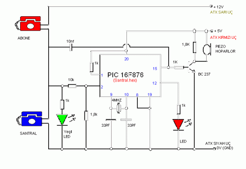
This simple telephone switching system is designed by Dr. Mustafa Kemal Peker for training purposes. All responsibility belongs to the user. Schematic and circuit details are included. The telephone switching system designed for training purposes serves as an educational tool...