
Simple Telephone Central Project
The telephone switching system designed for training purposes serves as an educational tool to understand the basic principles of telecommunication switching. This system typically consists of a series of components that facilitate the routing of calls from one line to another, simulating real-world telephone exchanges.
The primary components of the schematic include a power supply unit, which provides the necessary voltage and current to the circuit. The switching mechanism can be implemented using electromechanical relays or solid-state devices such as transistors, depending on the design requirements and desired complexity.
The system may feature multiple input and output lines to accommodate several telephone connections. Each input line represents a telephone line, while the output lines correspond to the possible destinations for incoming calls. The switching logic is usually managed by a microcontroller or a dedicated switching IC, which processes the incoming signals and determines the appropriate routing based on user inputs.
Additionally, the circuit may incorporate signal conditioning elements such as filters and amplifiers to ensure clear audio quality during calls. Protection components like diodes can be included to safeguard against voltage spikes and ensure the longevity of the circuit.
The schematic should also illustrate the connections between various components, including the arrangement of relays or transistors, the layout of the power supply, and the interconnections between the telephone lines and the switching logic. This detailed representation is crucial for understanding how the system operates and for troubleshooting any potential issues that may arise during usage.
In conclusion, this telephone switching system serves as an effective educational platform, providing users with hands-on experience in telecommunication technology while emphasizing the importance of understanding circuit design and functionality.This simple telephone switching system is designed by Dr. Mustafa Kemal PEKER for training purposes. All responsibility is belong to user. Schematic and c.. 🔗 External reference
Related Circuits
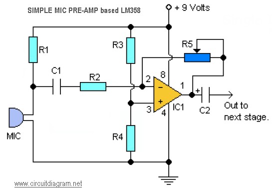
This is a simple audio microphone preamplifier circuit based on a single LM358 IC. The circuit is straightforward, cost-effective, and easy to construct. The component parts list includes: R1, R3, R4 = 10K; R2 = 1K; R5 = 100K-1M...
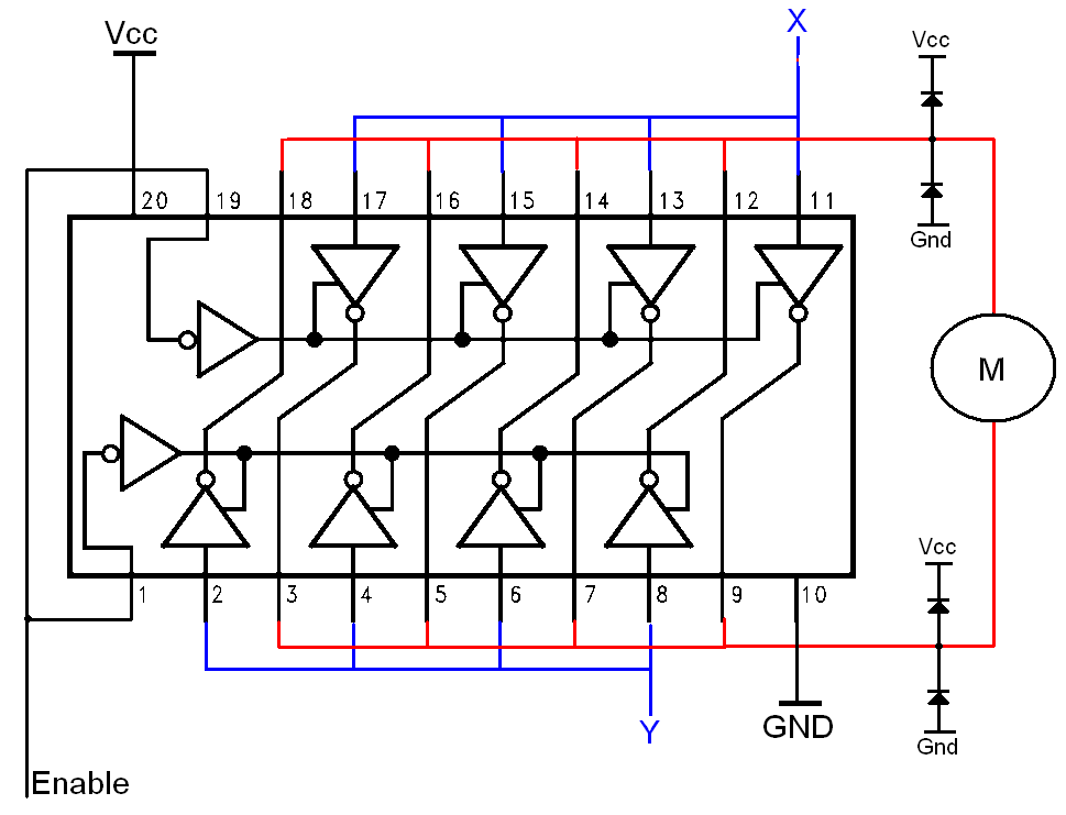
The H-bridge is a well-known and widely used circuit configuration for driving brushed DC motors. It enables straightforward control of motor direction, allowing for both forward and reverse operation. The H-bridge circuit consists of four switches, typically implemented using transistors...
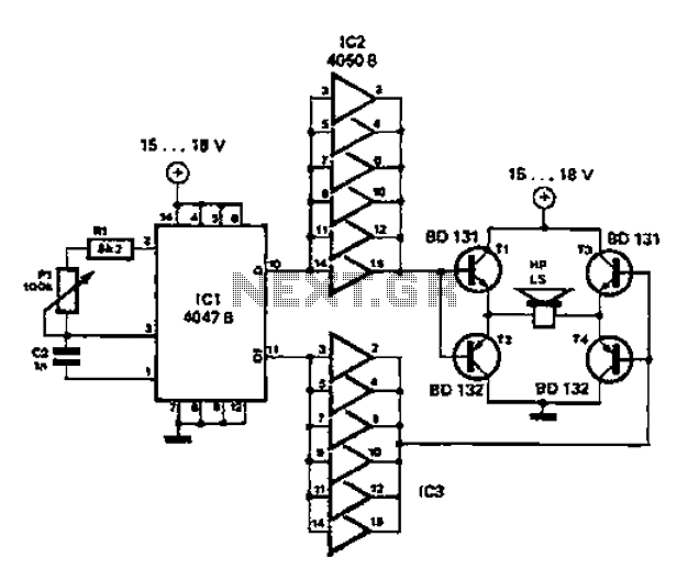
A low-cost and straightforward repellent circuit can be utilized for deterring rats, mice, and other animals, as illustrated in the electronic figure below. The circuit employs a CMOS integrated circuit of type 4047, which functions as a relaxation oscillator....
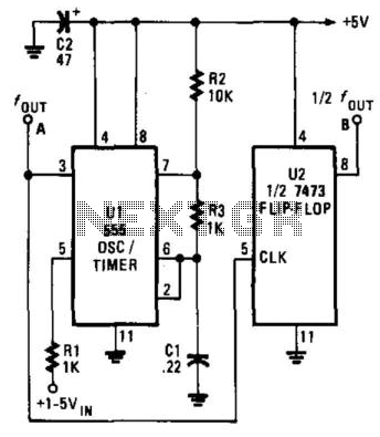
The Voltage-Controlled Oscillator (VCO) has an output frequency that ranges from 1500 Hz at Vcontrol = 1 V to 300 Hz at Vcontrol = 5 V. The resistive component R1 or the capacitive component C1 can be adjusted to...
.png)
This document describes a simple engineering project circuit for a mobile cell phone detector (sniffer). This compact mobile communication detector can sense the presence of a mobile device, making it suitable for preventing mobile phone usage in private spaces,...
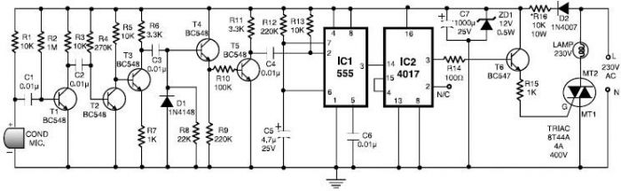
This 555 timer clap switch circuit electronic project is designed using common electronic components. The circuit operates from a distance of up to 10 meters from the microphone. The signal from the microphone is amplified by transistors T1, T2,...