
Simple Polarity Tester
The polarity tester circuit typically consists of a few basic components: a power source, a diode, an LED indicator, and resistors. The circuit is designed to be connected to the power source under test, which can be a battery or any DC power supply.
When the circuit is connected, the diode allows current to flow in one direction only, which is determined by the polarity of the power source. If the positive terminal of the power source is connected to the anode of the diode and the negative terminal to the cathode, the diode will conduct, allowing current to flow through to the LED indicator. The LED will light up, indicating that the polarity is correct.
Conversely, if the connections are reversed, the diode will block the current flow, preventing the LED from lighting up. This simple yet effective design provides a clear visual indication of the power source's polarity.
The inclusion of a resistor in series with the LED is essential to limit the current flowing through the LED, preventing damage from excessive current. The resistor value can be calculated based on the forward voltage of the LED and the supply voltage to ensure optimal performance.
Due to the simplicity of this circuit, it is cost-effective and can be easily built or repaired, making it a practical tool for automotive and electronic applications. The robustness of the design also allows it to withstand occasional overvoltage situations without significant damage, ensuring longevity and reliability in various testing scenarios.This tester can be used to check the polarity of any power source, and is therefore very useful when installing automotive equipment, alarm systems or anything else you can think of. Because this circuit is so simple and cheap, even frying one with an over voltage is not a big deal. 🔗 External reference
Related Circuits
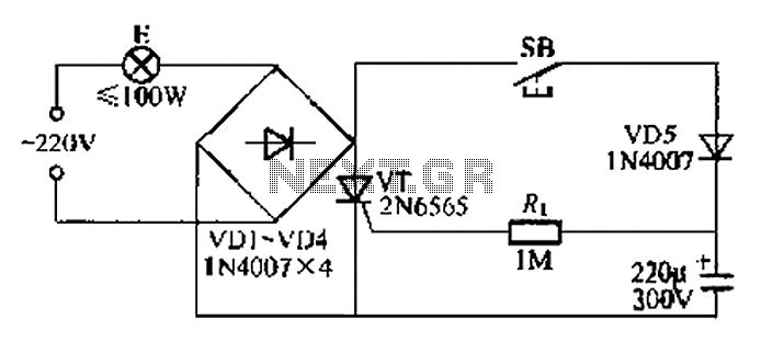
This circuit is a simple connection delay lamp circuit. When the lights are turned on and the switch is pressed, the power supply is activated. The capacitor charges rapidly, causing the thyristor (VT) to open, which in turn lights...
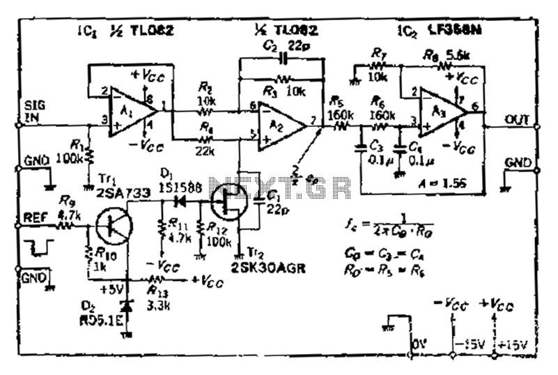
After turning off TT2, the input signal enters through chi Az, where the input resistance is very high and reaches the same potential. The inverting input terminal must also be associated with this movement. Therefore, Trr functions as a...
This circuit utilizes the well-known and easily accessible LM3914 integrated circuit (IC). The IC is straightforward to operate, requiring no external voltage regulators due to its built-in voltage regulation capability, and can be powered by a variety of sources....
This circuit is not a novelty, but it proved so useful, simple and cheap that it is worth building. When the positive (Red) probe is connected to a DC positive voltage and the Black probe to the negative, the...
If a negative supply is required for an operational amplifier or if a negative bias voltage is needed while operating from a single supply voltage, such as in battery applications. To generate a negative supply voltage from a single positive...
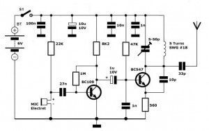
Simple FM Transmitter Circuit This simple FM transmitter circuit was built using a transistor with a transmission distance of about 300m around your home. The simple FM transmitter circuit utilizes a transistor to modulate audio signals onto a radio frequency...
Warning: include(partials/cookie-banner.php): Failed to open stream: Permission denied in /var/www/html/nextgr/view-circuit.php on line 713
Warning: include(): Failed opening 'partials/cookie-banner.php' for inclusion (include_path='.:/usr/share/php') in /var/www/html/nextgr/view-circuit.php on line 713