
Simple FM Modulator Design

The design of an FM transmission system involves several key components, including oscillators, modulators, amplifiers, and antennas. The oscillators, which have already been constructed, are crucial as they generate the carrier signals at specific frequencies within the FM band, typically ranging from 88 MHz to 108 MHz.
To achieve multi-frequency transmission, a frequency synthesizer may be employed, allowing for precise tuning and stability across the desired frequency range. This can be accomplished using phase-locked loops (PLLs) or direct digital synthesis (DDS) techniques, which provide flexibility in frequency selection and modulation.
The modulation stage is essential for encoding the audio or data signal onto the carrier wave. This is typically achieved using a voltage-controlled oscillator (VCO) that varies its frequency based on the amplitude of the input audio signal, effectively creating frequency modulation. The modulated signal is then amplified using RF amplifiers to ensure adequate power for transmission.
The final stage involves the antenna, which must be designed to efficiently radiate the modulated signal into the surrounding environment. The choice of antenna type (e.g., dipole, monopole, or loop) will depend on the desired range and coverage area of the transmission.
Careful consideration must also be given to compliance with regulatory standards governing FM transmissions to avoid interference with other services and ensure proper licensing. Power levels, frequency stability, and bandwidth must all adhere to the relevant guidelines to maintain operational integrity and legality.
Overall, the successful implementation of an FM transmission system requires meticulous design and integration of these components to achieve reliable and high-quality signal transmission.Hello, I want to build a system that can transmit in the FM band. I have already built my oscillators because I want to transmit at more than one.. 🔗 External reference
Related Circuits
This circuit is not a novelty, but it proved so useful, simple and cheap that it is worth building. When the positive (Red) probe is connected to a DC positive voltage and the Black probe to the negative, the...
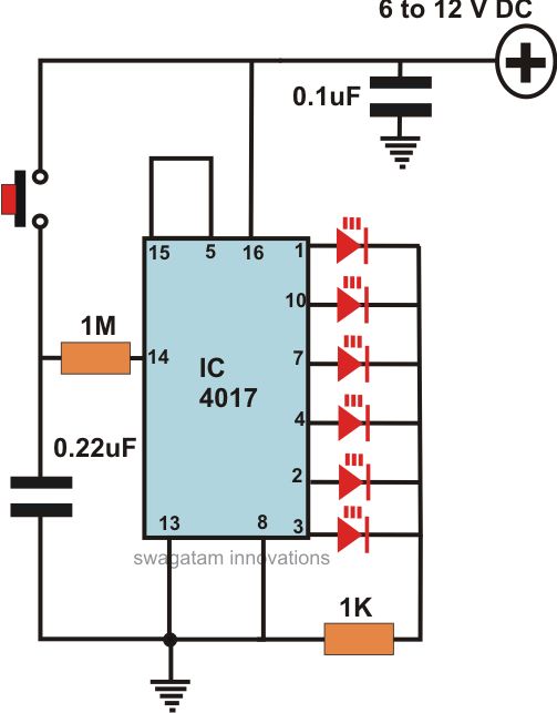
This article offers a circuit diagram and a discussion on CMOS logic and IC layout for creating a set of attention-getting LED running lights. It details a simple sequential LED flasher or light chaser that can be built, including...
There is a modification to the RC delay circuits that some may want to consider. If a shorter discharge time is desired, this modification enables the circuit to restart more quickly. The modification to the RC delay circuit involves adjusting...

Designing a power supply that meets the requirements of Power over Ethernet (PoE) and Voice over Internet Protocol (VoIP) applications can be complex. The low-component-count power supply illustrated in the figure complies with these specifications without requiring intricate circuitry....
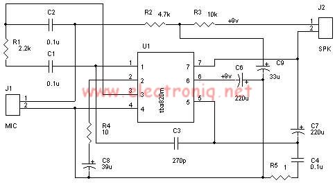
A very simple audio amplifier circuit can be designed using the TBA820M audio amplifier integrated circuit with just a few electronic components. This audio amplifier project features a high gain that allows for the detection of sounds underwater. The...
If a negative supply is required for an operational amplifier or if a negative bias voltage is needed while operating from a single supply voltage, such as in battery applications. To generate a negative supply voltage from a single positive...