
simple fm transmitter

The FM transmitter circuit typically consists of a few key components: an oscillator, a modulator, an amplifier, and an antenna. The oscillator generates a radio frequency signal, which is then modulated with the audio signal that is to be transmitted. The modulation process alters the frequency of the carrier wave in accordance with the audio input, allowing the sound to be transmitted over the airwaves.
The circuit may include a transistor or an integrated circuit (IC) as the main active component. A common choice for the oscillator is the Colpitts oscillator configuration, which provides stable frequency generation. The modulation can be achieved using a capacitor coupling method, where the audio signal is fed into the base of the transistor, affecting the oscillation frequency.
In terms of components, a few resistors and capacitors are required to set the operating frequency and stabilize the circuit. The choice of the antenna is also critical, as a well-designed antenna can significantly enhance the transmission range. A simple dipole or monopole antenna can be used, depending on the desired range and frequency.
Power supply considerations must also be addressed, as the circuit requires a stable voltage to function effectively. A battery or a regulated power supply can be employed, ensuring that the transmitter operates without fluctuations that could affect performance.
Overall, this simple FM transmitter circuit is an excellent project for those interested in learning about radio frequency transmission and modulation techniques, providing a practical application of electronic principles.Schematic and description to make fm transmitter. It is a simple fm transmitter circuit with minimum components but it has a long range. .. 🔗 External reference
Related Circuits

This involves controlling servo motors through software programming using the PIC 16C71 microcontroller. The input signals range from 0 to 5V. The circuit utilizes the PIC 16C71 microcontroller, which is an 8-bit device suitable for controlling servo motors. The microcontroller...

Simple FM Transmitter Circuit This simple FM transmitter circuit was built using a transistor with a transmission distance of about 300m around your home. The simple FM transmitter circuit utilizes a transistor to modulate audio signals onto a radio frequency...
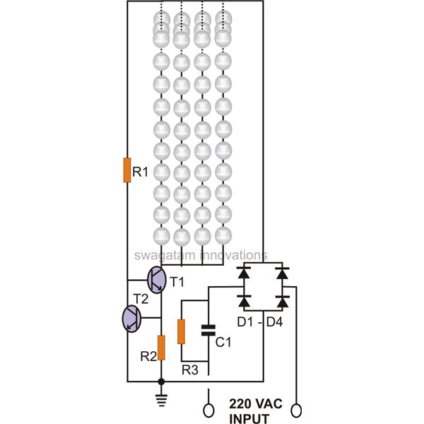
The circuit of a current-controlled LED tube light employs high-voltage transistors to implement the necessary current control operation based on a fundamental principle. A resistor (R2) is utilized to convert the increasing current into a voltage across itself. This...

This circuit explains alternate wireless switching using an ultrasonic sensor. The distance of the switching range should be more than 10 meters. The described circuit employs an ultrasonic sensor to facilitate wireless switching, allowing for the activation or deactivation of...

The circuit presented here represents one half of a device that is highly useful for tracing electrical wiring paths in buildings or locating breaks in wires. This system is based on equipment commonly used by technicians in telephone exchanges....

A simple lab power supply electronic project can be designed using this circuit diagram, which is based on the LM2576 monolithic integrated regulator that provides all the active functions for a step-down (buck) switching regulator. As seen in the...