
Simple Low-Frequency Receiver

The described circuit employs an NE602 integrated circuit as a heterodyne detector, which is a key component in radio frequency (RF) applications. The NE602 is designed to perform mixing and detection, facilitating the conversion of RF signals to intermediate frequencies (IF) suitable for further processing. In this configuration, U1 serves as the RF amplifier, enhancing weak incoming signals within the specified frequency range of 150 to 250 kHz. This amplification is crucial for improving the signal-to-noise ratio before the signal is fed into the NE602 for detection.
The heterodyne detection process involves mixing the incoming RF signal with a local oscillator signal within the NE602. This mixing generates two new frequencies: the sum and the difference of the original frequencies. The difference frequency, which falls within the audible range, is typically selected for further amplification and processing. The NE602's internal architecture allows for effective filtering and amplification of the desired signal, minimizing unwanted noise and interference.
U2, designated as the loudspeaker amplifier, is responsible for driving the output to a loudspeaker, allowing the demodulated audio signal to be heard. This stage typically includes additional filtering and amplification to ensure that the output audio is clear and adequately powered for the loudspeaker. The overall design of this receiver circuit is optimized for low-frequency reception, making it suitable for applications such as amateur radio, experimental audio transmission, or low-frequency broadcasting.
To enhance performance, careful attention should be given to component selection, layout, and grounding practices. Additionally, the choice of local oscillator frequency and the quality of the RF amplifier can significantly impact the receiver's sensitivity and selectivity. Proper shielding and filtering techniques may also be implemented to further reduce interference from other RF sources. Using an NE602 heterodyne detector and Ul as an RF amplifier, this receiver tunes the middle portion of the l ow-frequency spectrum from 150 to 250 kHz. U2 is a loudspeaker amplifier.
Related Circuits
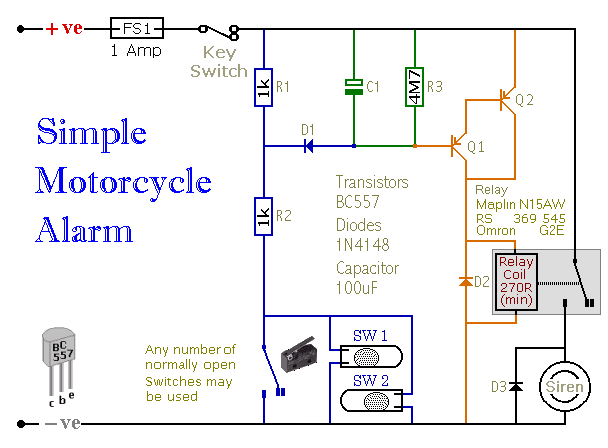
When one of the switches is closed, the base of Q1 is connected to ground through D1 and R2. This activates Q1, which in turn activates Q2. Q2 connects the positive side of the relay coil to the supply...
The circuit diagram represents a simple yet effective intercom system entirely based on transistors. It consists of three stages along with an RC amplifier. When the pushbutton S2 is pressed, the amplifier circuit around transistor T1 is activated. The intercom...
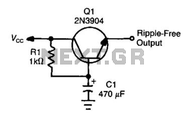
This circuit, often referred to as a capacitance multiplier, is effective for reducing power supply ripple. The capacitance provided by the circuit is equivalent to a capacitor of ( +1) Ci, where Ci represents the capacitance and the gain...
Since I have provided the schematic for John L Linsley-Hood's Class-A amplifier, I felt that some readers may wish to experiment with the concept. Unfortunately, a very low ripple power supply is needed for all Class-A amps, and the...
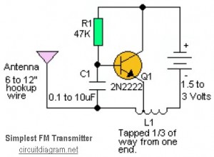
This is likely the simplest radio transmitter available. It comprises five components and can be assembled in a compact space. It is ideal for science fair projects or other science-related activities where short-range transmission is beneficial. The device operates...
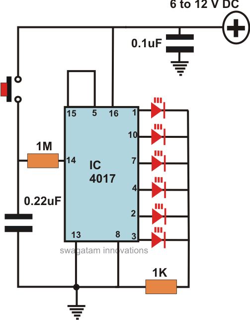
This article offers a circuit diagram and a discussion on CMOS logic and IC layout for creating a set of attention-getting LED running lights. It details a simple sequential LED flasher or light chaser that can be built, including...