
Simple RF Detector For 2M

The circuit operates by utilizing a simple yet effective design that allows for the detection of RF radiation. The antenna captures the RF signals, which are then tuned to resonance through the combination of capacitor C1 and inductor L1. The rectification process performed by diode D1 converts the RF signal into a usable form for amplification. The Darlington amplifier configuration, comprising transistors T2 and T3, ensures that even weak signals are amplified sufficiently for detection.
The LED readout system provides a clear visual indication of RF levels, with four distinct stages to inform the user of the intensity of the radiation detected. The integration of the UM66 sound/melody generator chip enables an audible alert for high radiation levels, enhancing the usability of the device in practical scenarios.
Adjustability is a key feature of this circuit, allowing users to tailor the sensitivity and response of the tester based on specific requirements. The zener diodes (D2, D4, D6, D8) serve as voltage reference points, enabling users to fine-tune the step size and overall span of the instrument's readout. This flexibility is particularly beneficial for operators working across different frequency bands, as the resonant network can be easily modified to accommodate various amateur radio frequencies.
The construction of inductor L1 from enameled copper wire ensures a lightweight and compact design while maintaining effective performance. The absence of a core minimizes losses and enhances the quality of the signal being detected. The trimmer capacitor C1 allows for precise tuning, ensuring optimal performance at the desired frequency.
Powering the circuit with a 9-V battery provides a reliable source of energy, while the low current draw of approximately 15 mA ensures extended operational life. Enclosing the circuit in a metal case not only protects the components but also helps shield the device from external RF interference, improving measurement accuracy.
Overall, this RF radiation tester circuit provides a practical solution for amateur radio operators and technicians, enabling them to identify potential issues with their equipment and ensure compliance with RF safety standards.This simple circuit helps you sniff out RF radiation leaking from your transmitter, improper joints, a broken cable or equipment with poor RF shielding. The tester is designed for the 2-m amateur radio band (144-146 MHz in Europe). The instrument has a 4-step LED readout and an audible alarm for high radiation voltages. The RF signal is picked up by an antenna and made to resonate by C1-L1. After rectifying by diode D1, the signal is fed to a two-transistor high-gain Darlington amplifier, T2-T3. Assuming that a 10-inch telescopic antenna is used, the RF level scale set up for the LEDs is as follows: When all LEDs light, the (optional) UM66 sound/melody generator chip (IC1) is also actuated and supplies an audible alarm.
By changing the values of zener diodes D2, D4, D6 and D8, the step size and span of the instrument may be changed as required. For operation in other ham or PMR bands, simply change the resonant network C1-L1. As an example, a 5-watt handheld transceiver fitted with a half-wave telescopic antenna (G=3. 5dBd), will produce an ERP (effective radiated power) of almost 10 watts and an e. m. f. of more than 8 volts close to your head. Inductor L1 consists of 2. 5 turns of 20SWG (approx. 1mm dia) enameled copper wire. The inside diameter is about 7mm and no core is used. The associated trimmer capacitor C1 is tuned for the highest number of LEDs to light at a relatively loweldstrength put up by a 2-m transceiver transmitting at 145 MHz.
The tester is powered by a 9-V battery and draws about 15mA when all LEDs are on. It should be enclosed in a metal case. 🔗 External reference
Related Circuits
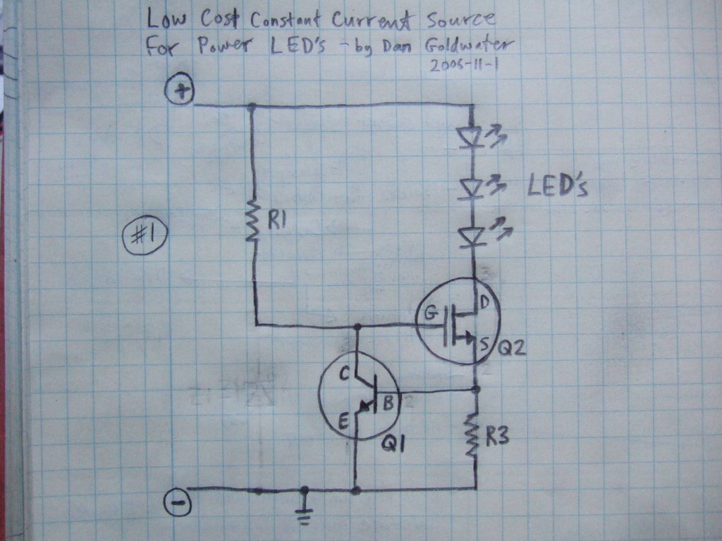
Here is a simple and inexpensive ($1) LED driver circuit. The circuit functions as a constant current source, ensuring that the LED maintains consistent brightness. The LED driver circuit is designed to provide a stable current to the LED, which...
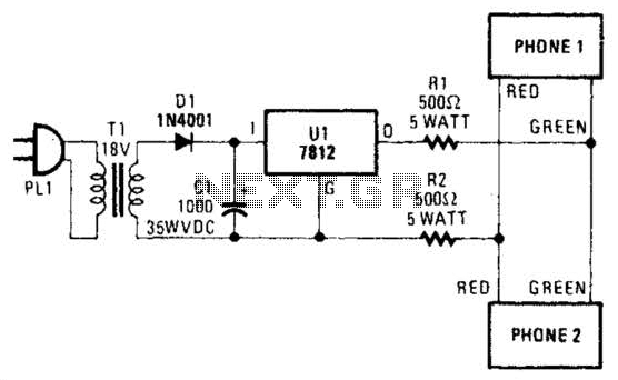
Two telephones can be used as an intercom by utilizing this circuit. Older style rotary phones that are non-electronic may be the most suitable for this application. Additionally, handsets alone can be powered in this manner. This intercom circuit allows...

This homemade metal detector circuit is designed to locate objects made of materials with relatively high magnetic permeability. While it may not be sensitive enough for detecting buried coins, it can effectively identify larger metallic treasures. The circuit operates...

The circuit described is suitable for indicating the capacity of a battery using a low-cost electric clock. By connecting a resistor across the battery terminals, the battery discharges at a faster rate than it would with the clock alone....
The circuit is designed for conducting safe experiments with high-voltage pulses and operates similarly to an electrified fence generator. The pulse repetition frequency (PRF) is dictated by the time constant of the R1-C3 network within the feedback loop of...
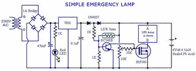
This is an automatic emergency lamp equipped with daylight sensing capabilities, enabling it to detect darkness and automatically turn on. Conversely, it senses daylight and turns off automatically. This straightforward emergency lamp does not require any special equipment, not...