
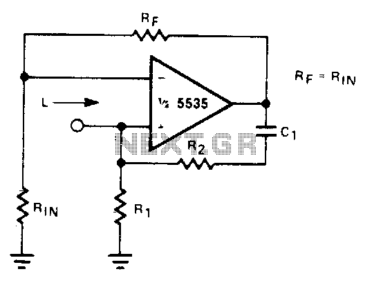
Simulated inductor

In this circuit, the effective inductance is determined by the relationship of the resistors R1 and R2, along with the capacitor C. The expression L = R1R2C indicates that the inductance is a product of the resistors and capacitance, highlighting the interdependence of these components. The quality factor (Q) is a critical parameter that defines the performance of the inductive circuit, influencing both the bandwidth and resonance characteristics. When Rj is set equal to R2, it optimizes the Q factor, enhancing the circuit's responsiveness to frequency changes.
However, the feedback mechanisms within the amplifier must be carefully managed. The equal feedback paths can lead to oscillations or instability, particularly at higher frequencies where the gain of the circuit may increase significantly. To mitigate this risk, it is essential that R1 is maintained at a value slightly less than R2, which helps to stabilize the feedback loop and maintain consistent performance across the operating frequency range. This design consideration is crucial for applications requiring reliable inductive behavior without the adverse effects of instability.
In summary, this circuit design emphasizes the careful selection of component values to achieve desired inductive characteristics while ensuring stable operation, particularly in the presence of varying frequencies.With a constant current excitation, the voltage dropped across an inductance increases with frequency. Thus, an active device whose output increases with frequency can be characterized as an inductance. The circuit yields such a response with the effective inductance being equal to: L = R1R2C. The Q of this inductance depends upon Rj being equal to R2. At the same time, however, the positive and negative feedback paths of the amplifier are equal leading to the distinct possibility of instability at high frequencies.
R1 should therefore always be slightly smaller than R2 to assure stable operation.
Related Circuits
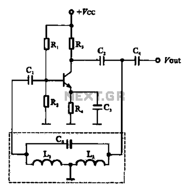
A three-point oscillator, also known as a Hartley oscillator, is similar to the Colpitts oscillator; however, its feedback circuit consists of two series inductors and a capacitor. The three-point oscillator is a type of electronic oscillator that generates sine waves....
With a constant current excitation, the voltage across an inductance increases with frequency. Therefore, an active device whose output increases with frequency can be characterized as an inductance. The circuit exhibits this response with the effective inductance defined as:...
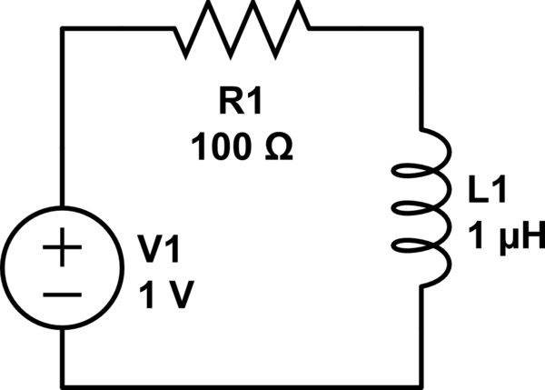
Consider a circuit consisting of a voltage source, a resistor, and an inductor arranged in a closed loop. When the voltage source is activated, the circuit reaches a steady state, during which the inductor stores energy calculated by the...
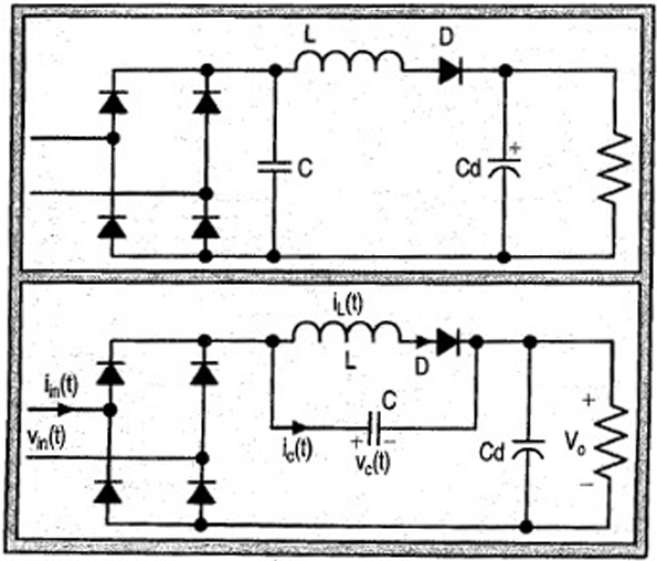
The input current for a passive power factor correction (PFC) circuit is not affected by variations in the output ripple, resulting in the need for a smaller inductance compared to earlier circuit designs. Passive power factor correction circuits are utilized...
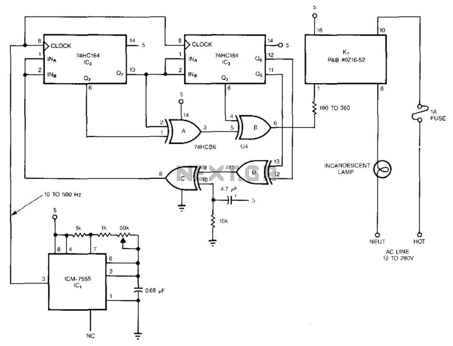
The pseudorandom sequencer drives a solid-state relay. When a low-wattage lamp is powered from the relay, the lamp will flicker like a candle's flame in the wind. Using higher-wattage lamps allows for the simulation of a fireplace or campfire...
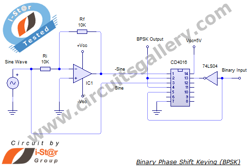
In a binary phase shift keying (BPSK) modulation scheme, the phase of a carrier signal is altered according to digital pulse signals. The BPSK modulator functions as a phase modulator, where the transmitted signal is a sinusoid with a...