
Sine Wave Generator (1KHz Frequency)
")
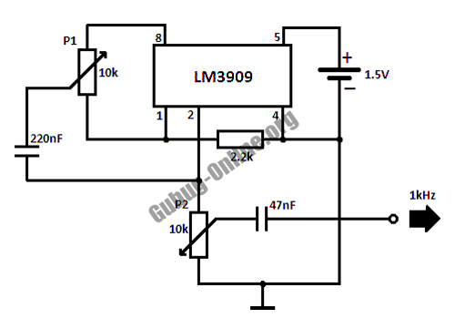
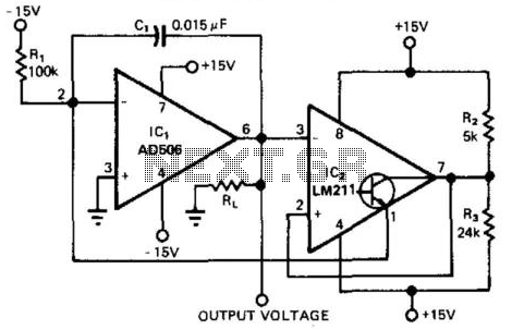
The described kHz sine wave generator circuit utilizes an inverted Wien bridge oscillator configuration, which is known for its stability and low distortion in generating sine waves. The circuit consists of two capacitors (C1 and C2) and four resistors (R3, R4, R5, and R7). The Wien bridge configuration is effective in producing a precise frequency output, which can be adjusted by modifying the resistor and capacitor values.
In this circuit, the resistors R5 and R7 play crucial roles in determining the output amplitude. R5 is specifically set to achieve a desired output voltage of 1V RMS when measured with an audio millivoltmeter, ensuring that the output signal meets the requirements for various audio applications. The adjustment of R7 allows for fine-tuning of the amplitude, providing flexibility in the output signal's strength.
The capacitors C1 and C2, in conjunction with the resistors, help establish the frequency of oscillation. The frequency can be calculated using the formula f = 1 / (2πRC), where R is the equivalent resistance and C is the capacitance. By selecting appropriate values for these components, the frequency can be accurately set within the desired kHz range.
Overall, this sine wave generator circuit is an effective solution for applications requiring stable sine wave signals, such as in audio testing, signal processing, and waveform generation. The straightforward design allows for easy implementation and adjustment, making it suitable for both experimental and practical uses in electronics.This is iKHz sine wave generator circuit built based on configuration of inverted Wien bridge (see C1-R3 C2-R4). R5 and R7 used for output amplutide setting. Set R5 to read 1V RMS on an Audio Millivoltmeter connected to the output with R7 ro.. 🔗 External reference
Related Circuits
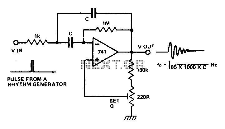
The circuit is a multiple feedback bandpass filter. A brief click (pulse) causes it to resonate at its natural frequency. The oscillations diminish exponentially, closely resembling various naturally occurring percussive or plucked sounds. The higher the quality factor (Q),...
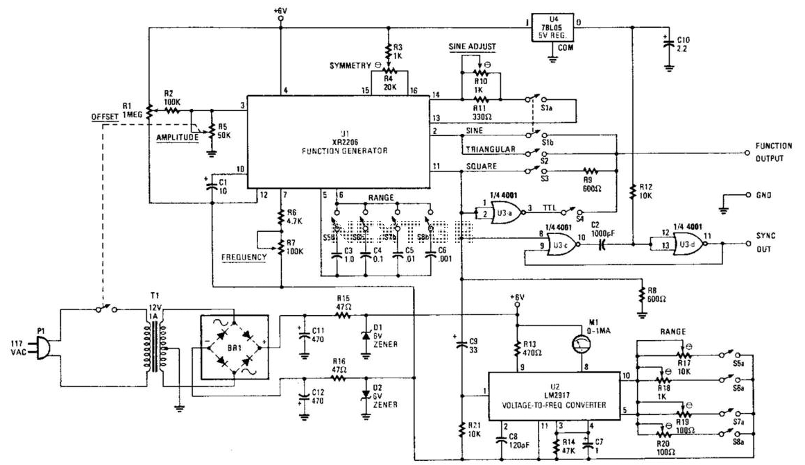
Using an EXAR XR2206, this generator will produce sine, square, and triangular waves from 10 Hz to 100 kHz. The XR2206 chip, R7 controls frequency, and S5 through S8 select the frequency range. U3 produces a TTL-compatible square-wave output,...
My generator can produce sine- and squarewaves with frequencies between 1 Hz and 100 kHz and amplitudes ranging from zero to 1.55 Veff in 600 Ohms. Sinewave distortion is 0.1% or less between 20 Hz and 20 kHz, somewhat...
This circuit design for a high-frequency waveform generator is highly beneficial for electronic experiments and designs. The circuit generates sine wave oscillations, but it can also be modified to produce triangle or square wave functions. The high-frequency waveform generator circuit...
This circuit provides a 0-to-10-V output excursion from 0.4 Hz to 100 kHz, characterized by its simplicity and compact size. The negative current through Rl generates a positive slope for the ramp and causes the output of IC1 to...
The SK1901 is a semiconductor integrated circuit that employs the Hall effect. It is specifically designed to function in alternating magnetic fields, particularly at low supply voltages and across a wide temperature range, up to +125°C. This Hall integrated...