
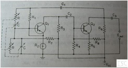
Single Pentode Wien Bridge Oscillator

The Wien Bridge oscillator is a critical component in audio frequency generation, relying on the principles of feedback and stability. The fundamental operation revolves around the balance of resistive and capacitive elements that define the oscillation frequency. The use of a two-stage amplifier with negative feedback is essential to maintain the desired gain while minimizing distortion. The inclusion of a light bulb as an amplitude stabilizer is a novel approach that allows for automatic adjustment of gain, ensuring that the output remains stable under varying conditions.
In practical applications, the Wien Bridge oscillator is favored for its ability to produce low-distortion sine waves, making it suitable for audio testing and generation. The design's reliance on linear amplification is crucial, as non-linear amplifiers would introduce unwanted harmonics and distortion. The careful selection of components, including the dual control pentode, ensures that the system can achieve the necessary gain without compromising the integrity of the oscillation.
Moreover, the Wien Bridge oscillator's low Q factor results in a more stable and predictable output compared to RF LC oscillators. This stability is particularly advantageous in audio applications where signal fidelity is paramount. The oscillator's design can be adapted for various frequency ranges by selecting appropriate resistor and capacitor values, providing versatility in its usage.
In summary, the Wien Bridge oscillator represents a sophisticated solution for audio frequency generation, characterized by its low distortion, stability, and innovative use of components such as the light bulb for gain stabilization. Its design principles and operational characteristics make it a valuable tool in the field of electronics, particularly in audio engineering and signal processing.His oscillator sought to use resistors and capacitors instead of bulky low frequency LC tank circuits to generate audio frequencies. He obtained low distortion (<0. 5%) with the use of a two stage amplifier with enough negative feedback to set it`s gain to just 3, as required for oscillation of the Wien Bridge circuit.
He used a light bulb to serve as amplitude detector and linear gain setting resistor for the fed-back amplifier . Hewlett credits L. A. Meacham with the use of the light bulb for automatic oscillator gain stabilization as published in the Bell System Technical Journal Vol 17, p. 574, 0ctober 1938. The Wien Bridge network was invented by Max Wien in 1891. This excerpt from Hewlett`s thesis shows half the bridge. At the resonant frequency with equal resistors and capacitors, the attenuation is 1/3 of the input voltage with zero phase shift.
This means that if an exact gain of 3 can be provided from the output of the network to the input, we have a sinusoidal oscillator. The simplified circuit on the right shows the lamp that stabilizes the non-inverting gain of the fed-back amplifier to exactly 3x.
The lamp resistance increases when a larger signal is applied to it. This means that if oscillations grow too large, the lamp resistance increases to reduce oscillation amplitude until a stable equilibrium is reached. At this equilibrium point, the RC-CR Wien network forces a gain of 3x at the fed-back amplifier, which is to say, it forces the lamp resistance to a value that yields an amplifier gain of 3x.
In turn, the Lamp forces the Wien network oscillation amplitude. This lamp stabilized Wien bridge oscillator differs fundamentally from RF LC oscillators commonly used in Radio circuits in that the oscillation currents and voltages in the Wien oscillator always remain nearly perfectly sinusoidal. Typical RF oscillators with an LC tank circuit have a very pure sine wave voltage across the the tank circuit, but the oscillations are stimulated with very non-linear current pulses in a class C regime.
The high Q>100 of the LC tank circuit gives the Frequency of these RF oscillators a fair immunity from variations in the strength of the current pulses that stimulate the oscillations. The amplitude of these Class C RF oscillators is controlled by the self limitation of the current pulses or by localized AGC action on these current pulses.
As the plot above shows, the Wien bridge circuit has a very low Q. If a class C amplifier were used instead of the linear amplifier with a gain of 3, the oscillation frequency would be not only a function of the RC-CR network time constants, but also a function of the class C amplifier limiting characteristics. It is essential then that the gain-of-3 amplifier be a very linear amplifier to let the RC-CR network time constants be the sole determinants of the oscillation frequency.
One inconvenience of the Wien bridge oscillator is that it requires a non-inverting gain amplifier, which, in the tube era generally meant a cascade of two inverting stages. This often made the phase shift oscillator which requires an inverting gain, a good alternative for a single tube RC oscillator design.
But Phase-shift oscillators require typically 4 or more RC pairs to obtain the 180o phase shift. The non-inverting voltage gain that is possible between the suppressor grid G3 and the screen grid G2 in a dual control Pentode can be used to build a Wien Bridge oscillator with a single Pentode. The following schematic shows the 6AS6 dual control pentode serving as the linear gain controlled amplifier with a gain of 3 from the suppressor grid G3 at pin 7 to the screen grid G2 at pin 6.
The exact gain of 3 from G3 to G2 is controlled automatically with the DC bias at the control grid 🔗 External reference
Related Circuits
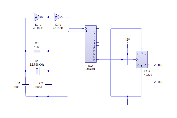
This plugin utilizes a quartz oscillator featuring a crystal (X1) to produce a 32,768 Hz (32,768 = 2^15) output. This frequency is fed into a 4020 14-Stage Ripple Counter, which divides the signal by 2^14, resulting in a 2...
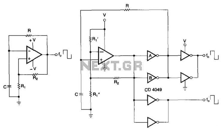
CMOS buffers added to an operational amplifier oscillator enhance performance, primarily due to the asymmetry and variability of the operational amplifier's output saturation voltages. The integration of CMOS buffers into an operational amplifier (op amp) oscillator circuit serves to significantly...

This design circuit functions as a sine wave oscillator, providing both sine and square wave outputs across a frequency range from below 20 Hz to above 20 KHz. The oscillation frequency can be easily adjusted by varying a single...
This article explains the construction and working of feedback oscillators, with a detailed description of the Wien bridge oscillator and phase shift oscillator, along with their circuit diagrams, basic components, and practical applications. Oscillators are electronic devices that produce...
The circuit serves as a foundational design, requiring experimentation for specific applications. In popular microwave bands, local oscillators (LOs) are typically generated using overtone crystal oscillators followed by multipliers. A table presents the standard LO frequencies for narrowband segments,...
Create an H-Bridge for controlling a DC brushed motor using PWM. One bridge will control one DC motor. The bridge will have three inputs: A, B, and PWM. Inputs A and B will determine the direction of the motor,...