
Single Transistor Metal Locator

The metal locator circuit operates by generating an oscillating signal that can be influenced by the presence of metal. The one-transistor oscillator is a critical component that produces a radio frequency signal. When metal is nearby, it alters the characteristics of the oscillation, which can be detected by the AM radio receiver.
The circuit typically consists of a few key components: a transistor, resistors, capacitors, and an inductor. The transistor is configured in a feedback loop to maintain oscillation. The inductor, often in the form of a coil, is used to create a magnetic field that interacts with metal objects. The AM radio serves as the output device, receiving the modulated signal created by the oscillator.
To enhance the sensitivity and range of detection, the circuit can be tuned by adjusting the values of the capacitors and resistors. This allows the user to optimize the circuit for various types of metal or different environmental conditions. The design is relatively straightforward, making it suitable for hobbyists and educational purposes.
Overall, this metal locator circuit is an effective tool for detecting metallic objects, leveraging the principles of radio frequency oscillation and modulation.This is a metal locator circuit. This circuit is useful to detect metal. This circuit uses a AM radio and one-transistor oscillator. This circuit is.. 🔗 External reference
Related Circuits

This circuit generates an FM modulated signal with an output power of approximately 500 mW. The microphone preamplifier is constructed using two 2N3904 transistors, with audio gain controlled by a 5 kΩ preset resistor. The oscillator is a Colpitts...

The E1T counting tube is one of the most fascinating tubes ever created. Developed by Philips between 1946 and 1954, it has a unique origin story detailed in other studies. A primary challenge in using this tube for clock...
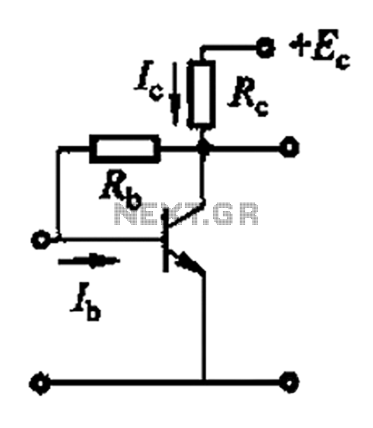
Basic reference bias circuit using a transistor with negative voltage feedback. The basic reference bias circuit utilizing a transistor with negative voltage feedback is designed to provide a stable output voltage or current that is largely independent of variations in...

The circuit diagram illustrates the connection of all three components of the series resonant crystal and triple CD4049 inverter. The supply voltage range is between 3 to 15 volts, making it suitable for various applications. This design is compact...

This is an improved version of a headphone amplifier I built many years ago. I wanted to share it because this simple circuit has done great service to me through all these years. It is very simple and reliable,...
The operating voltage of white LEDs coupled with my emotional need for low cost for a given function, motivates me to make LED drivers suitable for battery operated lanterns that can run from a small number of cells. White...