
Small DC-DC Inverter: Convert 1.5 to 9 volts

The 1.5 to 9 volts inverter circuit is designed to convert a low DC input voltage into a higher DC output voltage, specifically in the range of 1.5 to 9 volts. The circuit typically consists of a few essential components, including a transformer, transistors, resistors, capacitors, and a diode, which work together to achieve the desired voltage conversion.
The operation of the inverter circuit begins with the input voltage being applied to the base of a transistor, which acts as a switch. When the transistor is activated, it allows current to flow through the primary winding of the transformer. The transformer then induces a higher voltage in the secondary winding due to electromagnetic induction. The output voltage can be adjusted by selecting the appropriate turns ratio of the transformer.
To ensure stable operation and to prevent voltage spikes, capacitors are often included in the circuit. These capacitors filter the output, smoothing any fluctuations in voltage. Additionally, a diode may be used to prevent reverse current flow, protecting the circuit from potential damage.
This inverter circuit is versatile and can be utilized in various applications, including powering small electronic devices, charging batteries, and providing backup power for low-voltage equipment. Its simplicity and low cost make it an attractive option for hobbyists and professionals alike. Proper attention to component ratings and circuit layout is essential for optimal performance and reliability.This is a 1.5 to 9 volts inverter schematic circuit. This is low cost and a simple circuit that need few components.This circuit is used in many application. 🔗 External reference
Related Circuits
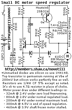
Reverse engineered circuit diagram of a motor speed regulator out of a portable pocket tape recorder containing a single motor for all functions. This circuit works amazingly well, keeping the motor speed constant regardless of shaft load and battery...
Chapter 4, part five of a five-part series titled "Some Thoughts on DC/DC Converters," authored by the late Jim Williams and Brian Huffman, is included in Volume II of the book "Analog Circuit Design-- Immersion in the Black Art...
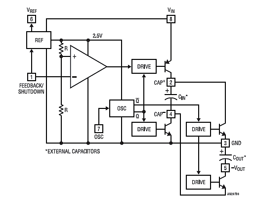
A DC/DC converter IC from Linear Technology, the LT1615 step-up switching voltage regulator, is capable of generating an output voltage of up to +34V from a supply voltage ranging from +1.2V to +15V, utilizing only a few external components....
This FM transmitter circuit is compact, similar to a previous single-chip FM transmitter, but it is monophonic in nature. The circuit can be observed in the provided schematic. This monophonic FM transmitter is designed to operate on a single frequency,...
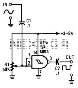
This circuit converts a sine wave into a square wave. It consists of a single 2-input NAND Schmitt trigger configured as an inverter, with an adjustable trigger level at its input. As the input voltage exceeds the gate's trigger...
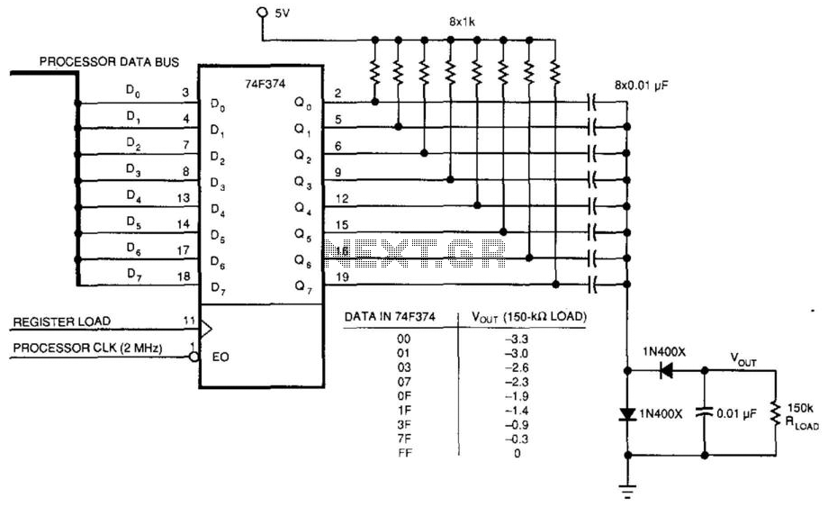
This circuit was used to produce a variable negative voltage for contrast control of an LCD display. A 74F374 generates a square wave that is AC coupled to a rectifier and load. By using the microprocessor clock and data...