
Smiths Tachometer
Direct connect electronic tachometers establish a direct electrical link with the ignition circuit, utilizing voltage signals to operate. In contrast, the inductively coupled types, such as the Smiths electronic tachometers from the 1960s, utilize a one-turn loop of ignition wire as the primary side of a transformer. This configuration allows current pulses from the ignition circuit to be coupled into the tachometer, with the timing of these pulses governing the tachometer's operation. These tachometers were commonly installed in vehicles like the Sunbeam Tigers, Alpines, and Shelby Cobras, among other British cars of that era.
The calibration or repair of the Smiths tachometer necessitates disassembly. The chrome bezel must be rotated until its tabs align with the slots on the case. This can be challenging, especially if the seals have deteriorated and become stuck. Care must be taken to avoid prying up the tabs, as this could damage the bezel. If necessary, gentle prying around the bezel may help loosen it, but tapping should be avoided due to the fragility of the meter. Once the chrome bezel is removed, the glass face and inner bezel may need to be detached if they did not come off with the outer bezel. It is not essential to separate the glass from the bezels if it is adhered to one of them. Extreme caution is advised during this process to prevent damage to the glass or bezels.
A source for replacement seals has not been identified, thus careful reuse of existing seals is recommended. Cleaning the glass with a lint-free cloth and glass cleaner is advisable while the tachometer is disassembled. Once the meter face is accessible, it is crucial to avoid smudging or leaving fingerprints on it, as well as preventing any damage to the needle.
To remove the tachometer's internal components, four screws located on the back of the case must be addressed. Of these, two screws are recessed and secure the internal assembly, while the other two are not. The latter should be removed carefully while supporting the internal components with fingers. Once the screws are out, the internal assembly can be gently lifted from the case. It is prudent to hold the assembly securely while catching the face of the tachometer with the other hand to prevent any drops.
With the tachometer's internal components exposed, calibration or debugging can commence. This is also an opportune moment to insert a shield under the needle to protect the face during any repainting of the needle, should suitable paint be available. The Smiths tachometer operates using a relatively simple design, incorporating two Germanium transistors in an inductively coupled configuration. The schematic diagram of the tachometer illustrates its electronic layout, although verification of the Zener diode symbol orientation may be required.Calibrating the Smiths electronic tachometer some time ago when I realized that my tach was completely out of calibration. I used a technique similar to the one described in Tom Ballous 1975 Tech Tip to calibrate my tach at about 1200RPM using my dwell/tach meter.
I began to wonder, however, how well calibrated my dwell/tach meter was and how well my Smiths tach was at high RPM. This curiosity led me to analyze how the Smiths tach works and to design a personal computer based tach calibration tool. This paper is intended to explain how the tachometer works, to explain how my tach calibrator works, and to update Tom Ballous Tech Tip with my opinions and advice.
Direct connect electronic tachs have a direct electrical connection to the ignition circuit. These tachs use voltage signals in the ignition circuit to drive the tach. The inductively coupled type of tach such as the Smiths electronic tachs of the 1960s uses a one turn loop of the ignition wire as the primary side of a transformer that couples the current pulses caused by the cars ignition circuit into the inside of the tach. The timing of those current pulses are used to drive the tach. These tachometers were used in Sunbeam Tigers and Alpines as well as in Shelby Cobras and other British cars of the period.
Since this is the tach Ive had the most experience with, this is the tach I will describe in detail. The Smiths tach must be disassembled in order to calibrate or repair it. Carefully rotate the chrome bezel until the tabs on the bezel line up with the slots on the case. This can be a very difficult job if the seals have aged badly and stuck. Whatever you do, DON`T pry up the tabs on the bezel or youll ruin it. If you need to, you can CAREFULLY pry a tiny bit around the bezel in an attempt to break it loose. Don`t tap the edge as the meter is very fragile. Once you get the chrome bezel off the tach, the face glass and inside bezel must come out, if they didn`t come out with the chrome bezel. Carefully pry the inner bezel from the case. It is not necessary to separate the glass from either bezel if it is stuck to one of them. Be careful prying on anything, especially if the glass is still in place, as it is very easy to damage it or the bezels.
I have not been able to locate a source for the seals, so I just try to be very careful, and reuse what I can with whats left of the seals. I always use a lint free cloth and glass cleaner to clean the glass while the tach is apart. Once the meter face is exposed, be very careful not to mar or get finger prints on the face or break the needle.
The next step is to remove the tach innards from the case. There are four screws on the back of the case, two of which are recessed in holes in the case and two of which are not. The two in the recessed holes hold the innards of the tach together so don`t take them out. Put the tach case face down on the bench. While pinching the U bracket stud with one finger and the power spade lug with another to hold up the tach innards, remove both of the non-recessed screws.
The tach innards are now being held in the case by your two fingers. Pick up the case and cup your other hand under the face of the case. Carefully let the stud and spade lug slide out of your fingers and catch the face of the tach by the edges in the cup of your hand. You can then pull the case off of the tach innards and turn it over. You are now ready to calibrate or debug the tach. This is a good time to slide a shield under the needle to shield the face and repaint the needle if you can find appropriate paint.
(My artistic talents arent very good, so I never try that step myself. ) Electronically, the Smiths tach is a relatively simple two Germanium transistor inductively coupled electronic tach. The following diagram shows the schematic of the tach: (I think I may have the Zener symbol upside down, BTW.
) The two transistors together form 🔗 External reference
Related Circuits
One of the goals of Movable Party is to provide an interactive experience for audiences and participants. Power will be generated from a hub motor attached to the rear wheel of each bike, with the speed of the rear...
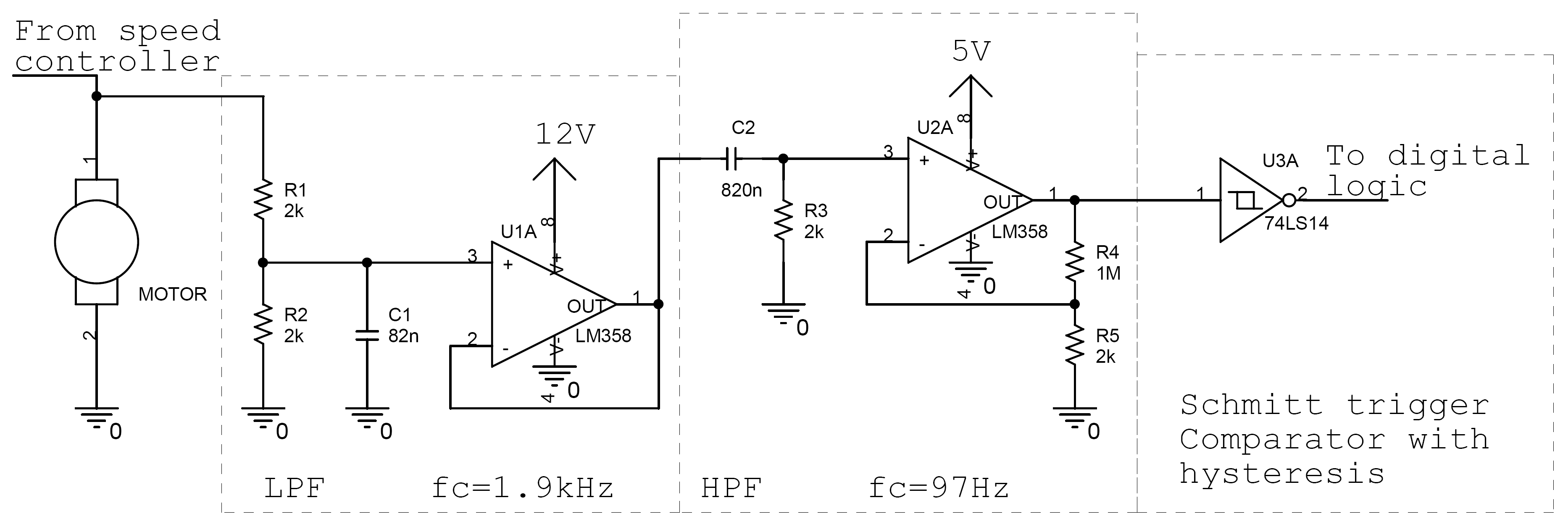
Controlling the speed of a motor is crucial in various applications, particularly in robotics. Numerous techniques exist for adjusting motor speed, each offering distinct advantages and disadvantages. This document outlines the construction of a motor controller that regulates the...
The tachometer, also known as a revolution counter, is an instrument that measures the speed of rotating machinery, typically expressed in revolutions per minute (RPM). This project involves creating a custom sensor using a light-emitting diode (LED) as a...
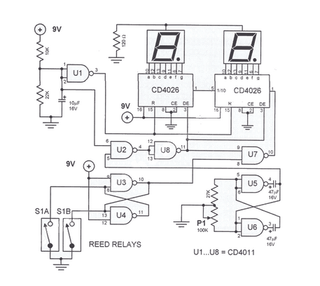
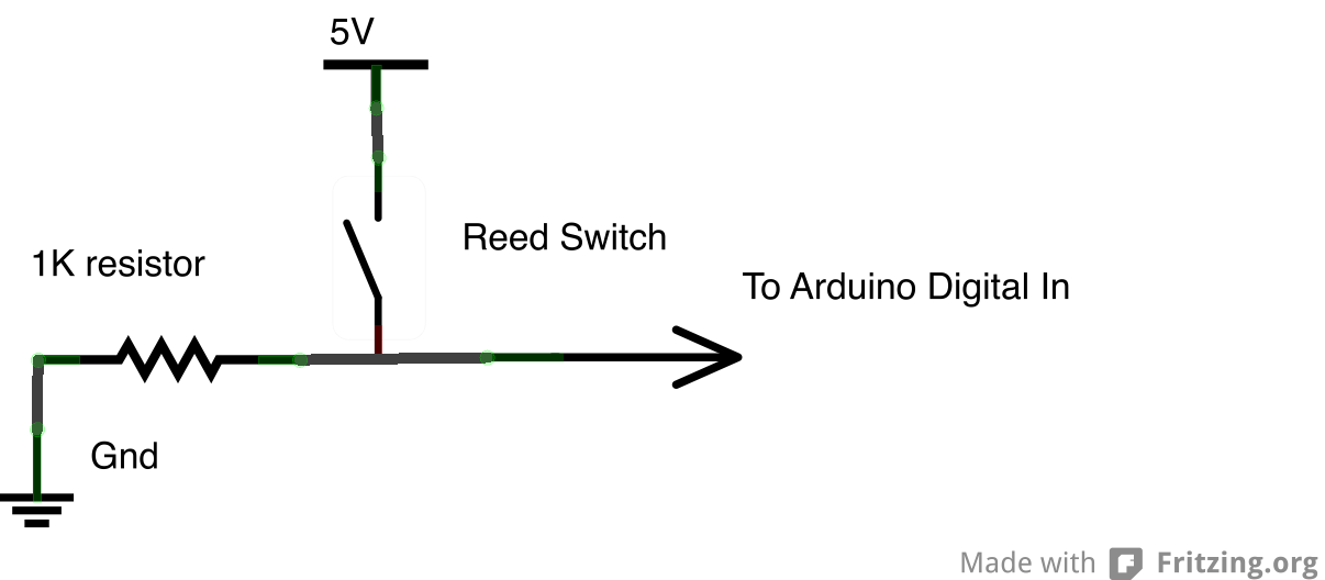
This digital DIY tachometer for bicycles utilizes two reed switches to obtain speed information. The reed switches are positioned near the rim of the wheel. The digital DIY tachometer circuit is designed to provide accurate speed measurements for bicycles by...
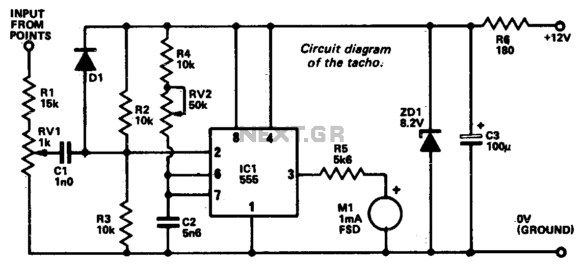
An electrical signal from the low tension side of the distributor is converted into a voltage that is proportional to engine RPM, and this voltage is displayed on a meter calibrated accordingly. The 555 timer integrated circuit (IC) operates...
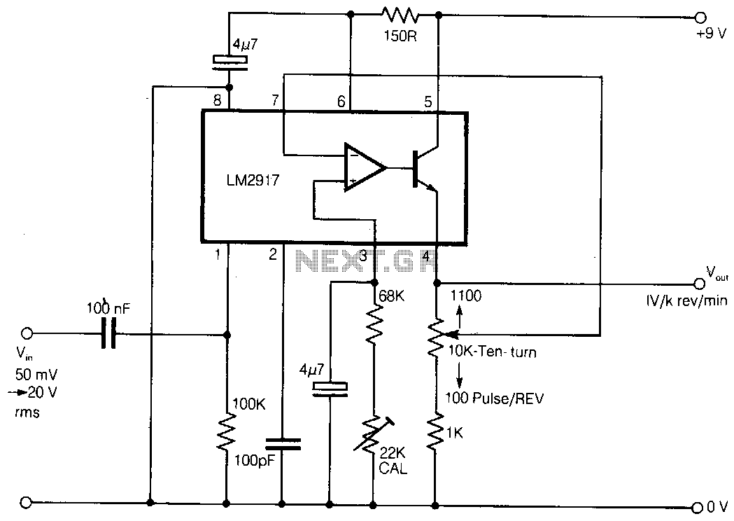
Here is a simple tachometer circuit for use with a hand-held DVM or portable chart recorder. A novel feature is that the source frequency pulse/rev rate can be directly set on a ten-turn potentiometer to provide a convenient calibration...